EasyManua.ls Logo

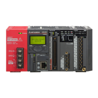
Mitsubishi MELSEC Q Series - User Manual

Mitsubishi MELSEC Q Series
664 pages
Print Icon
To Next Page IconTo Next Page
Loading...

Table of Contents

Other manuals for Mitsubishi MELSEC Q Series

Questions and Answers

  • C
    castanedaantonioSep 8, 2025
    What to do if I encounter a hardware error of the module in Mitsubishi I/O Systems?
    • C
      Christopher AyalaSep 9, 2025
      To resolve a hardware error with your Mitsubishi I/O Systems module, first, switch the power off and then on again. If the error persists after this, it may indicate a module failure. In such a case, it's recommended to consult with the Mitsubishi office for further assistance.
  • M
    Marcus YoderAug 25, 2025
    Why am I getting an overflow error on my Mitsubishi Controller?
    • S
      smcconnellAug 25, 2025
      An overflow error in your Mitsubishi Controller can occur if: 1) When a linear counter is in use, an add pulse is input beyond the current value of 2147483647. 2) When a linear counter is in use, a subtract pulse is input below the current value of -2147483647. To resolve this, preset the controller to clear the overflow error.
  • E
    Elizabeth RoseAug 25, 2025
    What to do if the input signal is not turned OFF on my Mitsubishi MELSEC Q?
    • A
      allisonalexanderAug 26, 2025
      If the input signal on your Mitsubishi Controller isn't turning OFF, it could be due to leakage current from the input switch. To resolve this, connect an appropriate resistor to lower the voltage across the input module terminals below the OFF voltage value. For AC input, it's recommended to use a CR constant with 0.1 to 47 F + 47 to 120 (1/2W). Another cause might be a limit switch with a neon lamp, in which case you can apply the same resistor solution or create an independent display circuit. Finally, leakage current from the wiring cable's line capacity could be the issue. The same resistor fix applies here, but note that leakage current isn't generated when the power supply is located on the input equipment side.
  • J
    Jennifer FitzgeraldSep 18, 2025
    What to check if (Gain value) - (Offset value) 0.1 in Mitsubishi I/O Systems?
    • W
      Whitney LutzSep 18, 2025
      To address this issue, check the voltage at the thermocouple input terminal.
  • E
    Eric BurnsNov 25, 2025
    What to do if an analog output value is not output on a Mitsubishi MELSEC Q Controller?
    • J
      james87Nov 25, 2025
      If your Mitsubishi Controller is not outputting an analog value, consider the following: - Ensure 24VDC is being supplied from the external power supply by verifying that 24VDC voltage is being supplied to the external power supply terminals. - Check for any faults with the analog signal lines, such as broken or disconnected lines, through visual and continuity checks. - Confirm the CPU module is in RUN status. If it's in STOP status, set it to RUN. - Verify that the offset/gain settings are correct. If the user range setting is being used, switch to a different default input range and check if D/A conversion is correctly performed. If it is correctly performed, redo the offset/gain settings. - Verify the setting range in GX Developer monitor. If the output range setting is incorrect, red...
  • A
    austinsaraSep 13, 2025
    What to do if conversion is made with another thermocouple set after setting of the offset/gain value in Mitsubishi I/O Systems?
    • C
      christine77Sep 13, 2025
      If conversion is made with another thermocouple set after setting of the offset/gain value, make offset/gain setting again after changing the thermocouple.
  • S
    Scott WrightSep 4, 2025
    What to do if the G(P).OGSTOR instruction was executed consecutively on Mitsubishi Controller?
    • J
      Jason MeyersSep 4, 2025
      Execute the G(P).OGSTOR instruction only once for one module. At the time of offset/gain setting, write a set value only once at one time.
  • A
    Alyssa WeaverSep 4, 2025
    How to solve scaling upper/lower limit value set outside the range of –32000 to 32000 on Mitsubishi Controller?
    • R
      Ryan BlackwellSep 4, 2025
      Correct the scaling upper/lower limit value within the range of –32000 to 32000.
  • D
    Dr. Aaron Andersen MDNov 24, 2025
    Why is the RUN LED turned off on my Mitsubishi MELSEC Q?
    • M
      Matthew JohnsonNov 25, 2025
      The RUN LED on your Mitsubishi Controller might be off due to several reasons: - There may be no power being supplied. Confirm that the supply voltage for the power supply module is within the rated range. - The capacity of the power supply module may be inadequate. Calculate the current consumption of the CPU module, I/O module, and intelligent function module mounted on the base unit to see if the power supply capacity is adequate. - A watchdog timer error may have occurred. Reset the programmable controller CPU and verify that it is lit. If the RUN LED does not light even after doing this, the module may be malfunctioning. Please consult your local Mitsubishi representative, explaining a detailed description. - The module may not be correctly mounted on the base unit. Check the mounti...
  • B
    Brandon LesterAug 30, 2025
    How to solve scaling lower limit value equal to or greater than the scaling upper limit value on Mitsubishi Controller?
    • T
      Thomas RomeroAug 30, 2025
      Set CH scaling upper/lower limit value so that the scaling upper limit value is greater than the scaling lower limit value.

Summary

CHAPTER1 OVERVIEW

1.1 Features

Describes the features of the C Controller module, including VxWorks, standard ROM, large data storage, and I/O control capabilities.

CHAPTER2 SYSTEM CONFIGURATION

2.1 System Configuration

Explains device configuration, development environment connection, and system configuration overview for C Controller systems.

2.1.1 Devices to be used

Details the base units, extension cables, power supply modules, and other components used with the C Controller module.

CHAPTER3 SPECIFICATIONS

3.1 General Specifications

Provides the general specifications of the C Controller module, including operating ambient temperature, humidity, vibration, and shock resistance.

CHAPTER4 FUNCTIONS

4.1 Function List

Lists the functions of the C Controller module, such as I/O module access, remote operation, and self-diagnostic functions.

CHAPTER5 SETTINGS AND PROCEDURES BEFORE OPERATION

5.1 Handling Precautions

Explains critical handling precautions for the C Controller module, including environment, installation, and connection safety.

CHAPTER6 I;O NUMBER ASSIGNMENT

6.1 Relation between No. of Base Units and No. of Slots

Explains how base units and slots relate to I/O number assignment for the C Controller module.

CHAPTER7 MEMORIES AND FILES HANDLED BY C CONTROLLER MODULE

7.1 Memory of C Controller Module

Explains user memories (Standard ROM, Work RAM, Battery-backed-up RAM, CompactFlash) and system memory.

CHAPTER8 INSTALLING AND UNINSTALLING SW[]PVC-CCPU

8.1 Development Environment

Details the product requirements for the development environment, including personal computer specifications and operating system.

CHAPTER9 UTILITY OPERATION

9.1 Common Utility Operations

Explains common operations for utilities, including starting, exiting, setting connection targets, and displaying help screens.

CHAPTER10 FUNCTIONS AND PROGRAMMING

10.1 Outline of Functions

Outlines bus interface functions and MELSEC data link functions supplied with SW PVC-CCPU for accessing modules and CPUs.

CHAPTER11 OVERVIEW OF MULTIPLE CPU SYSTEM

11.1 What is Multiple CPU System?

Defines the multiple CPU system concept, explaining how multiple CPU modules work together for enhanced performance.

CHAPTER12 MULTIPLE CPU SYSTEM CONFIGURATION

12.1 System Configuration

Explains system configuration for multiple CPU systems, including device compatibility and connection methods.

CHAPTER13 MULTIPLE CPU SYSTEM CONCEPT

13.1 Mounting Position of CPU Module

Details the mounting positions of CPU modules (C Controller, Basic QCPU, High Performance QCPU, Motion CPU) in a multiple CPU system.

CHAPTER14 COMMUNICATIONS BETWEEN CPU MODULES

14.1 Data Communications by MELSEC Data Link Functions

Explains data communication methods using MELSEC data link functions between CPU modules, including auto refresh and shared memory.

CHAPTER15 PARAMETERS ADDED FOR MULTIPLE CPU SYSTEM

15.1 Parameter List

Lists parameters required for multiple CPU system operation, highlighting setup necessity and consistency checks in the C Controller setting utility.

CHAPTER16 PRECAUTIONS FOR USE OF AnS SERIES MODULE

16.1 Precautions for Use of AnS Series Module

Provides specific precautions for using AnS series modules, including applicable I/O and special function modules and control CPU settings.

CHAPTER18 TROUBLESHOOTING

18.1 Troubleshooting Basics

Provides fundamental steps for troubleshooting, including visual checks, fault verification, and narrowing down the error cause.

Mitsubishi MELSEC Q Series Specifications

General IconGeneral
SeriesMELSEC Q Series
TypeModular PLC
Programming SoftwareGX Works2, GX Works3
CategoryProgrammable Logic Controller (PLC)
I/O ModulesDigital I/O, Analog I/O, High-Speed Counter, Positioning
CommunicationEthernet, CC-Link
Programming LanguagesLadder Logic, Structured Text, Function Block Diagram, Sequential Function Chart, Instruction List
MemoryFlash Memory
I/O PointsUp to 4096 points (expandable with additional modules)
Power SupplyAC or DC power supply options available, depending on the base unit and modules.
MountingDIN rail mounting
Operating Temperature0°C to 55°C
Storage Temperature-25°C to 75°C
Humidity5% to 95% (non-condensing)
Vibration Resistance10 to 57 Hz, 0.075mm amplitude
WeightVaries depending on the module, from a few grams to several kilograms.
Shock Resistance147 m/s² (3 times each in X, Y, Z directions)

Related product manuals