10
FUNCTIONS AND PROGRAMMING
10.3 Programming Using MELSEC Data Link Functions
10.3.10 Station No. setting for MELSEC data link functions
10 - 42
9
UTILITY OPERATION
10
FUNCTIONS AND
PROGRAMMING
11
OVERVIEW OF
MULTIPLE CPU
SYSTEM
12
MULTIPLE CPU
SYSTEM
CONFIGURATION
13
MULTIPLE CPU
SYSTEM
CONCEPT
14
COMMUNICATIONS
BETWEEN CPU
MODULES
15
PARAMETERS
ADDED FOR
MULTIPLE CPU
16
PRECAUTIONS FOR
USE OF AnS SERIES
MODULE
10.3.10 Station No. setting for MELSEC data link functions
The following indicates the station numbers set for the MELSEC data link functions.
* 1
* 2
* 3 For CC-Link communication, station No.64 cannot be specified.
When its own station No. is 64, the other station cannot be specified. (Access is allowed only to the own station.)
Table10.13 Station numbers specified for MELSEC data link functions
Communication Station number specification
Q series bus interface
Own station: 255(FFH)
Other station: 1 (CPU No.1), 2 (CPU No.2), 3 (CPU No.3),
4 (CPU No.4)
MELSECNET/H
Own station: 255(FFH)
Other station: *1
CC-Link
Own station: 255(FF
H)
Other station: 0(0
H) to 63(3FH), 65(41H) to 239(EFH)
*2, *3
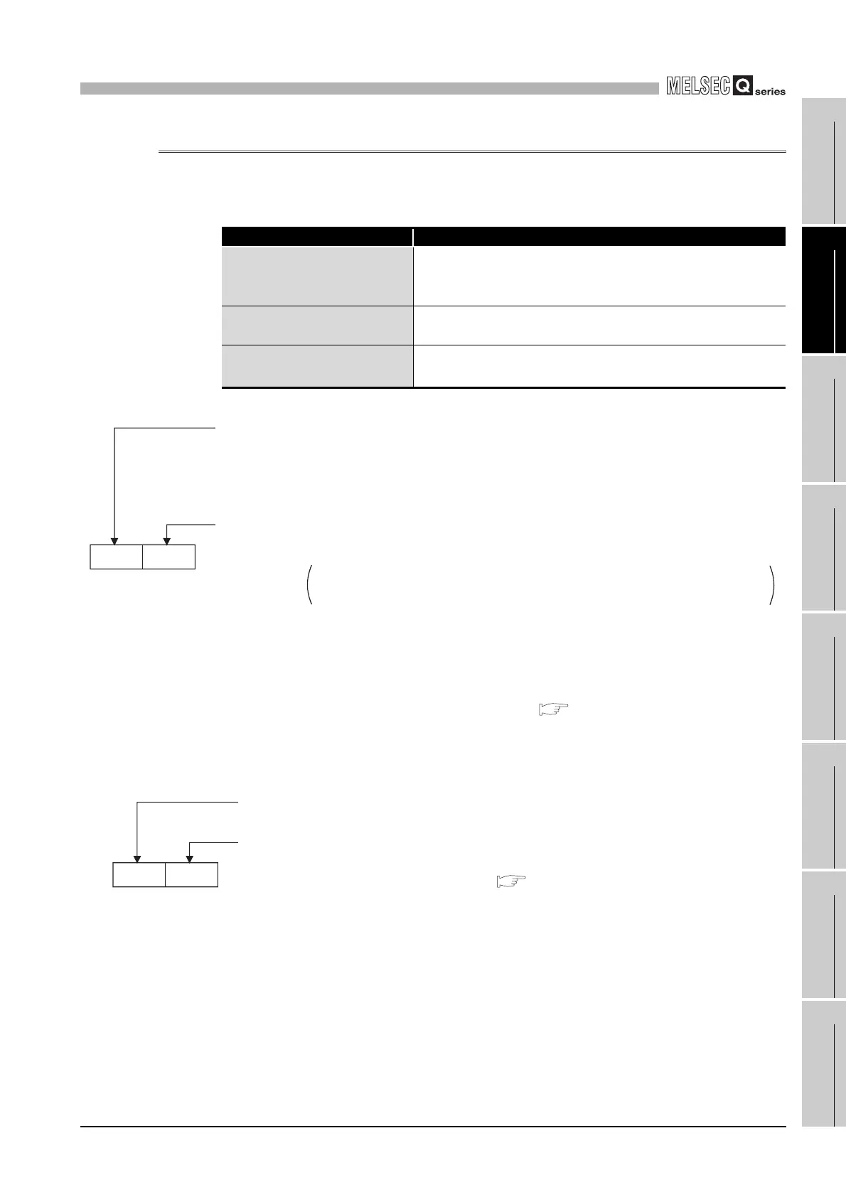
Figure 10.20 Station No. setting for MELSECNET/H module
Figure 10.21 Station No. setting for CC-Link module
Upper Lower
<Logical Sta. No. setting method>
Set "0" in the upper byte (network No.) of the above format, and specify a logical station No. in the
lower byte (station No.).
The setting range of logical station No. is 65(41
H) to 239(EFH).
Set the logical station No. on the <<Target setting>> tab of the MELSECNET/H utility.
Network No.
(In the case of send request to the MELSECNET/H or MELSECNET/10)
1(1
H) to 239(EFH): When specifying the other station in the local network or a station in other network
Station No., group No. or all stations
(The all stations specification is available only when the SEND (mdSend) function is used.)
240(F0
H) : All stations
Group No.1 to 9 (129(81
H) to 137(89H)) are used in the MELSECNET/10 mode when the
target CPU is the QnACPU.
The group No. specification is available only when the SEND (mdSend) function is used.
129(81
H) to 160(A0H): Group No.1 to 32
1(1
H) to 64(40H) : Other stations
( Section 9.4.7)
<Logical station No. setting method>
Set "0" in the upper byte (network No.) of the one shown left, and
specify the logical station No. in the lower byte (station No.).
The setting range of logical station No. is 65(41
H) to 239(EFH).
Set the logical station No. on the <<Target setting>> tab of the
CC-Link utility.
0(0H) ro 63(3FH) : Other station
Station No.
0: When CC-Link is used
Network No.
LowerUpper
( Section 9.3.6)

 Loading...


