4
FUNCTIONS
4.4 MELSECNET/H Module Access Function
4.4.5 Link data send/receive processing time specifications
4 - 34
1
OVERVIEW
2
SYSTEM
CONFIGURATION
3
SPECIFICATIONS
4
FUNCTIONS
5
SETTING AND
PROCEDURES
6
I/O NUMBER
ASSIGNMENT
7
MEMORIES AND
FILES
8
INSTALLING /
UNINSTALLING
4.4.5 Link data send/receive processing time specifications
This section explains how to calculate the link data send/receive time and transmission
delay time in the MELSECNET/H network system.
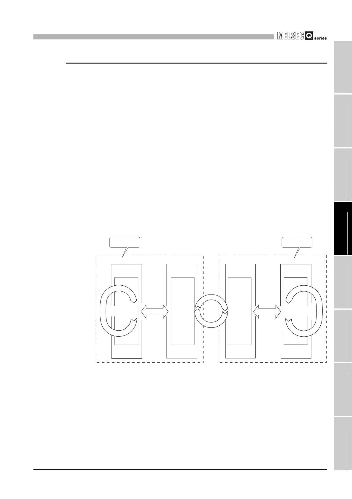
(1) Link data send/receive processing
(a) Outline of send/receive processing
Cyclic transmission uses LB/LW/LX/LY of the MELSECNET/H module to make
communications.
Here, the case of the C Controller module side link relay (B) is used for
explanation.
1) Turn ON B0 of the LB buffer (sending side).
2) Link device refresh stores the B0 information of the LB buffer into the link data
storage area (LB) of the MELSECNET/H module.
3) Link scan stores the B0 information of the link data storage area (LB) into the
link data storage area (LB) of the receiving side MELSECNET/H module.
4) Link device refresh stores the B0 information of the link data storage area (LB)
into the LB buffer of the C Controller module.
5) B0 of the LB buffer (receiving side) turns ON.
* 1 Set the refresh parameters for link device refresh.
* 2 Set the network range assignment parameters for link scan.
Figure 4.32 Link data send/receive processing
B0 turns ON.
1)
B0 turns ON.
5)
C Controller module
Internal link
device buffer
<LB buffer>
Link device
refresh cycle
C Controller module
Internal link
device buffer
<LB buffer>
Link device
refresh cycle
Link device
refresh
*1
*2 *2
2)
Link device
refresh
*1
4)
Link data
storage area
LB
MELSECNET/H module
Link data
storage area
LB
MELSECNET/H module
Link
scan
3)
Sending side Receiving side

 Loading...


