13
MULTIPLE CPU SYSTEM CONCEPT
13.1 Mounting Position of CPU Module
13 - 2
9
UTILITY OPERATION
10
FUNCTIONS AND
PROGRAMMING
11
OVERVIEW OF
MULTIPLE CPU
SYSTEM
12
MULTIPLE CPU
SYSTEM
CONFIGURATION
13
MULTIPLE CPU
SYSTEM
CONCEPT
14
COMMUNICATIONS
BETWEEN CPU
MODULES
15
PARAMETERS
ADDED FOR
MULTIPLE CPU
16
PRECAUTIONS FOR
USE OF AnS SERIES
MODULE
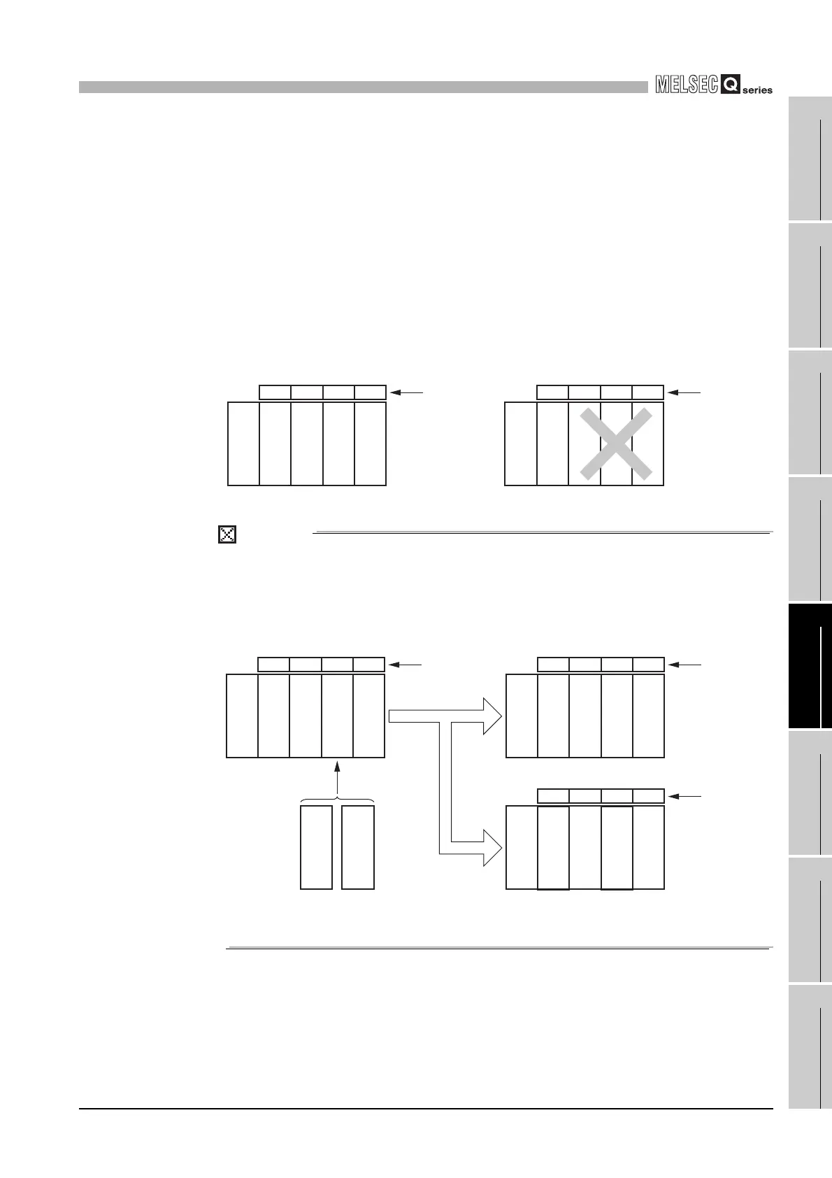
(c) "CPU (Empty)" setting
An empty slot can be reserved for future addition of a CPU module.
Set the number of CPU modules, including the one on the empty slot, in "No. of
CPU" on the <<Multiple CPU setting>> tab of the C Controller Setting Utility.
After that, set the type "CPU (Empty)" to the slot on the right side of the mounted
CPU module (s) on the <<I/O assignment setting>> tab of the C Controller setting
utility.
(Example) When the No. of CPUs is set to 4 in the Multiple CPU setting and two
C Controller modules and one Motion CPU are mounted
Mount the C Controller modules to the CPU slot and Slot 0 and the
Motion CPU to Slot 1, and set Slot 2 to "CPU (Empty)".
POINT
When the C Controller module is used, "CPU (Empty)" cannot be set between
CPU modules.
However, since no mounting position priorities are given between the C Controller
module and Motion CPU, either of them can be added without shifting the CPU
module at the right end.
Figure 13.1 "CPU (Empty)" setting
Figure 13.2 Addition of CPU module
CPU 0 1 2 CPU 0 1 2
Mounting allowed Mounting not allowed
Slot numbe
Slot number
Power supply
module
CPU (Empty)
Power supply
module
C Controller
module
C Controller
module
C Controller
module
Motion CPU
CPU (Empty)
C Controller
module
Motion CPU
CPU 0 1 2
Slot numbe
CPU 0 1 2
Slot numbe
CPU 0 1 2
Slot number
Addition
Either CPU module
can be added.
Power supply
module
C Controller
module
Motion CPU
Motion CPU
Power supply
module
C Controller
module
Motion CPU
Power supply
module
C Controller
module
CPU (Empty)
Motion CPU
C Controller
module
Motion CPU
C Controller
module

 Loading...


