14
COMMUNICATIONS BETWEEN CPU MODULES
14.3 Data Communications Using CPU Shared Memory
14.3.3 Data communications without using auto refresh
14 - 16
9
UTILITY OPERATION
10
FUNCTIONS AND
PROGRAMMING
11
OVERVIEW OF
MULTIPLE CPU
SYSTEM
12
MULTIPLE CPU
SYSTEM
CONFIGURATION
13
MULTIPLE CPU
SYSTEM
CONCEPT
14
COMMUNICATIONS
BETWEEN CPU
MODULES
15
PARAMETERS
ADDED FOR
MULTIPLE CPU
16
PRECAUTIONS FOR
USE OF AnS SERIES
MODULE
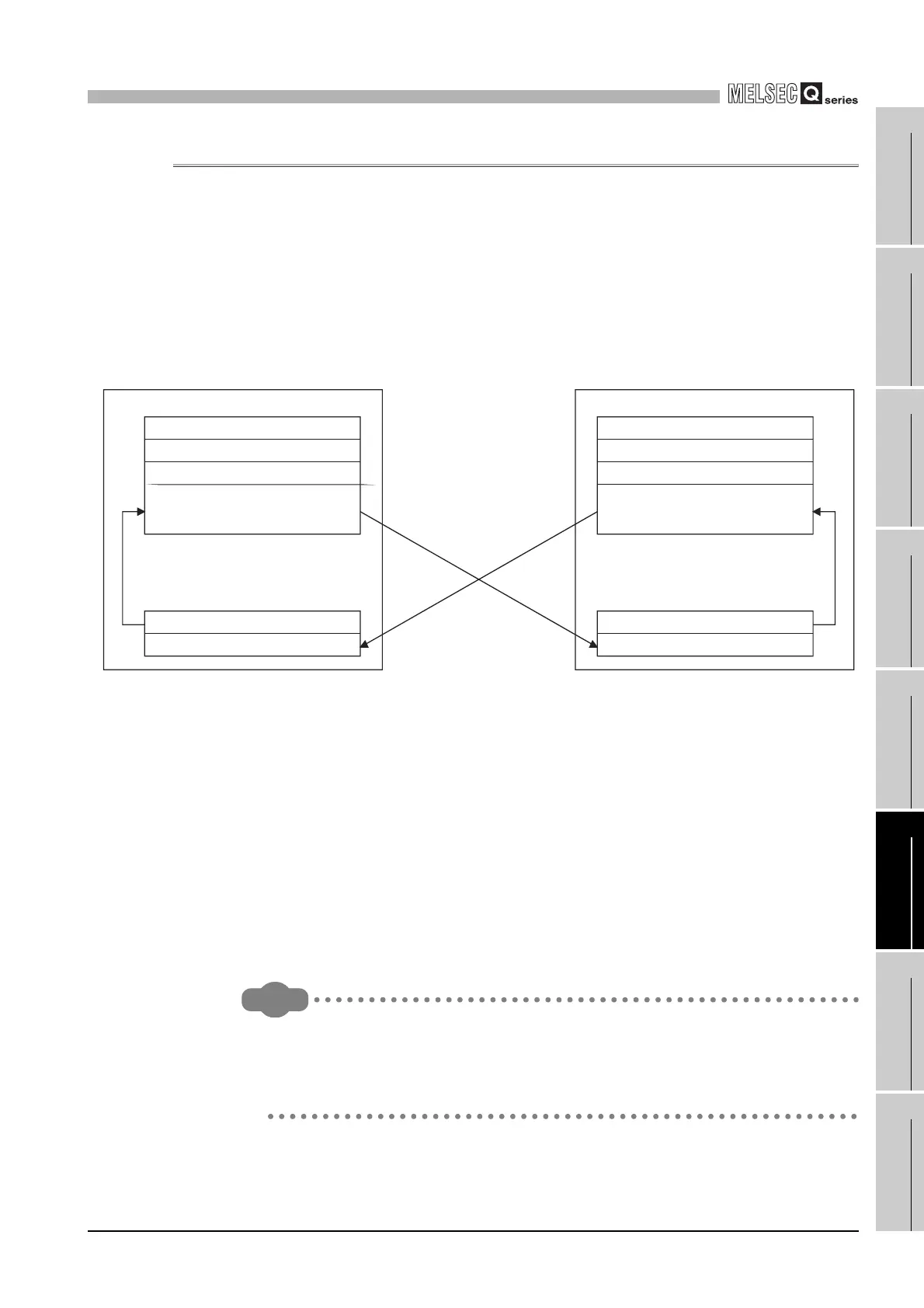
14.3.3 Data communications without using auto refresh
This section explains the processing of data communications using CPU shared memory
and without using the auto refresh of the programmable controller CPU.
(1) Processing of data communications without using auto refresh
The following indicates the processing of data communications made without using
auto refresh.
(a) Between programmable controller CPU and C Controller module
Remark
Figure 14.13 shows an operation example using the S.TO and FROM instructions
on the High Performance model QCPU.
Refer to the manual of the corresponding CPU module for the operation to be
performed when the auto refresh of the programmable controller CPU is not used.
Figure 14.13 Processing of communications without using auto refresh
CPU shared memory
Host CPU operation information area
System area
Auto refresh area
Data written by execution of
S.TO instruction (User free area)
1. Write by S.TO instruction of programmable
controller CPU
Sequence program
Execution of S.TO instruction
Execution of FROM instruction
Programmable controller CPU
Host CPU operation information area
System area
Auto refresh area
Data written by QBF_ToBuf function
(User free area)
CPU shared memory
User program
Execution of QBF_FromBuf function
Execution of QBF_ToBuf function
2. Write by QBF_ToBuf function
of C Controller module
C Controller module
3. Read by QBF_FromBuf
function of C Controller module
4. Read by FROM
instruction of programmable
controller CPU
Processing details at sequence program execution of programmable
controller CPU
The S.TO instruction writes data to the user free area of the programmable
controller CPU's CPU shared memory.
The FROM instruction reads the user free area data of the C Controller
module to the specified device of the programmable controller CPU.
1.
4.
Processing details at bus interface function execution of C Controller module
Execution of the QBF_ToBuf function writes data to the user free area
of the C Controller module's CPU shared memory.
Execution of the QBF_FromBuf function reads the user free area data
of the programmable controller CPU to the user program.
2.
3.

 Loading...


