EasyManua.ls Logo

Mitsubishi MELSEC Q Series User Manual

Mitsubishi MELSEC Q Series
664 pages
To Next Page IconTo Next Page
To Previous Page IconTo Previous Page
Page #506 background imageLoading...
Page #506 background image
13 - 15
13.4 Access Ranges between CPU Modules and Other Modules
13.4.2 Access to non-controlled modules
13
MULTIPLE CPU SYSTEM CONCEPT
13.4.2 Access to non-controlled modules
The CPU module can load the input (X) ON/OFF data of non-controlled modules and the
output (Y) ON/OFF data of other station CPUs by the parameters of the multiple CPU
setting.
Therefore, ON/OFF data of input modules, I/O composite modules or intelligent function
modules controlled by other CPUs can be used as interlocks for the host CPU, and the
output status to external equipment being controlled by other CPUs can be confirmed.
Also, the buffer memory contents of the non-controlled intelligent function modules can be
read, regardless of the parameters of the multiple CPU setting.
However, it is not possible for non-control CPUs to output ON/OFF data to non-controlled
output modules, composite I/O module or intelligent function modules, and to write data to
the buffer memory of intelligent function modules.
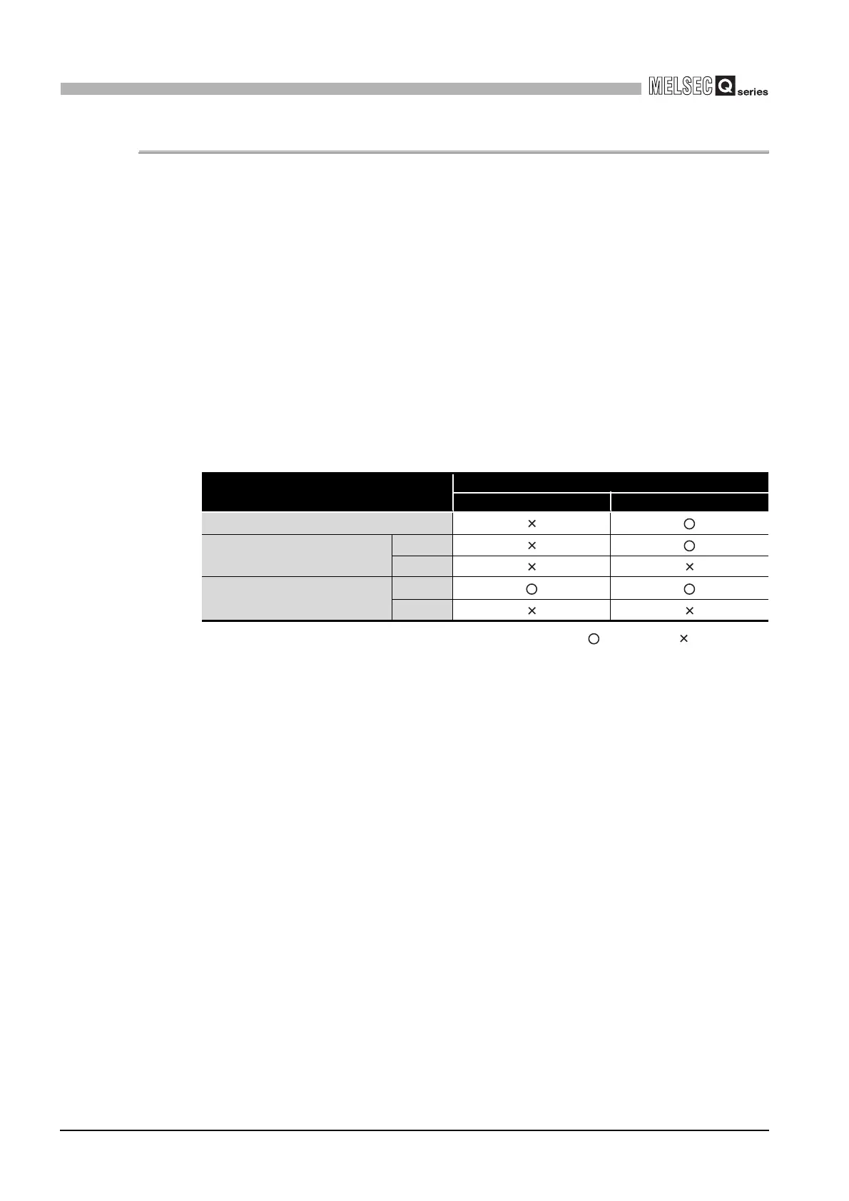
Table13.6 indicates accessibility to the non-controlled modules in the multiple CPU
system.
: Accessible : Inaccessible
* 1 Correct value cannot be read when the inputs (X) of the AnS series module controlled by the High
Performance model QCPU are read.
They are all OFF.
* 2 If data is read from the buffer memory of the AnS series module controlled by the High
Performance model QCPU, an offset error (return value: -208) occurs and data cannot be read.
Table13.6 Access range to non-controlled module
Access target
I/O setting outside of the group
Disabled (Not checked) Enabled (Checked)
Input (X)
*1
Output (Y)
Read
Write
Buffer memory of intelligent
function module
Read
*2
Write

Table of Contents

Other manuals for Mitsubishi MELSEC Q Series

Questions and Answers:

Mitsubishi MELSEC Q Series Specifications

General IconGeneral
SeriesMELSEC Q Series
TypeModular PLC
Programming SoftwareGX Works2, GX Works3
CategoryProgrammable Logic Controller (PLC)
I/O ModulesDigital I/O, Analog I/O, High-Speed Counter, Positioning
CommunicationEthernet, CC-Link
Programming LanguagesLadder Logic, Structured Text, Function Block Diagram, Sequential Function Chart, Instruction List
MemoryFlash Memory
I/O PointsUp to 4096 points (expandable with additional modules)
Power SupplyAC or DC power supply options available, depending on the base unit and modules.
MountingDIN rail mounting
Operating Temperature0°C to 55°C
Storage Temperature-25°C to 75°C
Humidity5% to 95% (non-condensing)
Vibration Resistance10 to 57 Hz, 0.075mm amplitude
WeightVaries depending on the module, from a few grams to several kilograms.
Shock Resistance147 m/s² (3 times each in X, Y, Z directions)

Summary

CHAPTER1 OVERVIEW

1.1 Features

Describes the features of the C Controller module, including VxWorks, standard ROM, large data storage, and I/O control capabilities.

CHAPTER2 SYSTEM CONFIGURATION

2.1 System Configuration

Explains device configuration, development environment connection, and system configuration overview for C Controller systems.

2.1.1 Devices to be used

Details the base units, extension cables, power supply modules, and other components used with the C Controller module.

CHAPTER3 SPECIFICATIONS

3.1 General Specifications

Provides the general specifications of the C Controller module, including operating ambient temperature, humidity, vibration, and shock resistance.

CHAPTER4 FUNCTIONS

4.1 Function List

Lists the functions of the C Controller module, such as I/O module access, remote operation, and self-diagnostic functions.

CHAPTER5 SETTINGS AND PROCEDURES BEFORE OPERATION

5.1 Handling Precautions

Explains critical handling precautions for the C Controller module, including environment, installation, and connection safety.

CHAPTER6 I/O NUMBER ASSIGNMENT

6.1 Relation between No. of Base Units and No. of Slots

Explains how base units and slots relate to I/O number assignment for the C Controller module.

CHAPTER7 MEMORIES AND FILES HANDLED BY C CONTROLLER MODULE

7.1 Memory of C Controller Module

Explains user memories (Standard ROM, Work RAM, Battery-backed-up RAM, CompactFlash) and system memory.

CHAPTER8 INSTALLING AND UNINSTALLING SW[]PVC-CCPU

8.1 Development Environment

Details the product requirements for the development environment, including personal computer specifications and operating system.

CHAPTER9 UTILITY OPERATION

9.1 Common Utility Operations

Explains common operations for utilities, including starting, exiting, setting connection targets, and displaying help screens.

CHAPTER10 FUNCTIONS AND PROGRAMMING

10.1 Outline of Functions

Outlines bus interface functions and MELSEC data link functions supplied with SW PVC-CCPU for accessing modules and CPUs.

CHAPTER11 OVERVIEW OF MULTIPLE CPU SYSTEM

11.1 What is Multiple CPU System ?

Defines the multiple CPU system concept, explaining how multiple CPU modules work together for enhanced performance.

CHAPTER12 MULTIPLE CPU SYSTEM CONFIGURATION

12.1 System Configuration

Explains system configuration for multiple CPU systems, including device compatibility and connection methods.

CHAPTER13 MULTIPLE CPU SYSTEM CONCEPT

13.1 Mounting Position of CPU Module

Details the mounting positions of CPU modules (C Controller, Basic QCPU, High Performance QCPU, Motion CPU) in a multiple CPU system.

CHAPTER14 COMMUNICATIONS BETWEEN CPU MODULES

14.1 Data Communications by MELSEC Data Link Functions

Explains data communication methods using MELSEC data link functions between CPU modules, including auto refresh and shared memory.

CHAPTER15 PARAMETERS ADDED FOR MULTIPLE CPU SYSTEM

15.1 Parameter List

Lists parameters required for multiple CPU system operation, highlighting setup necessity and consistency checks in the C Controller setting utility.

CHAPTER16 PRECAUTIONS FOR USE OF AnS SERIES MODULE

16.1 Precautions for Use of AnS Series Module

Provides specific precautions for using AnS series modules, including applicable I/O and special function modules and control CPU settings.

CHAPTER18 TROUBLESHOOTING

18.1 Troubleshooting Basics

Provides fundamental steps for troubleshooting, including visual checks, fault verification, and narrowing down the error cause.

Related product manuals