4 - 35
4.4 MELSECNET/H Module Access Function
4.4.5 Link data send/receive processing time specifications
4
FUNCTIONS
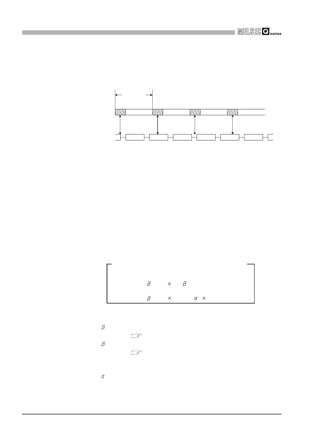
(b) Link scan and link device refresh
Link scan is performed "asynchronously" with the link device refresh of the C
Controller module.
The link device refresh is executed in the link device refresh cycles set for the C
Controller module.
(2) How to calculate transmission delay time
(a) Delay time in transmission within the same network
1) Cyclic transmission (LB/LW/LX/LY periodic communications)
The transmission delay time in B/W/Y communications is calculated with:
• Link device refresh cycles of the C Controller modules on the sending and
receiving stations
• Link device refresh times of the C Controller modules on the sending and
receiving stations
• Scan time (excluding the link refresh time) of the programmable controller
CPU (receiving side)
• Link refresh time of the programmable controller CPU (receiving side)
• Link scan time
And use the expression shown below.
L
T : Link device refresh cycle of C Controller module (sending side)
L
R : Link device refresh cycle of C Controller module (receiving side)
T : Total link devices refresh time of C Controller module (sending
side)
*1
( This section 2))
R : Total link devices refresh time of C Controller module (receiving
side)
*1
( This section 2))
S
R : Scan time (excluding link refresh time) of programmable controller CPU
(receiving side)
*2
R : Link refresh time of programmable controller CPU (receiving side)
*1,*2
LS : Link scan time
*2
Figure 4.33 Link scan and link device refresh
Link device
refresh
Link device
refresh
Link device
refresh
Link device
refresh
Link device
refresh
Link scan
Link device
refresh cycle
[Transmission delay time (TD1) of B/W/Y communications]
1) When the C Controller module (another CPU) receives data
(Until data are stored into internal link device buffer)
T
D1 = LT + T + (LS 1) + (SR+ R) 2 [ms]
T
D1 = LT + T + (LS 1) + R + LR [ms]
2) When a programmable controller CPU receives data

 Loading...


