5. PARAMETERS
5 - 38
Control
mode
No./symbol/
name
Setting
digit
Function
Initial
value
[unit]
P S T
_ _ x x Analog monitor 1 output selection
Select a signal to output to MO1 (Analog monitor 1). Refer to appendix 8 (3) for
detection point of output selection.
Refer to table 5.8 for settings.
00h PC14
MOD1
Analog
monitor 1
output
_ x _ _ For manufacturer setting 0h
x _ _ _ 0h
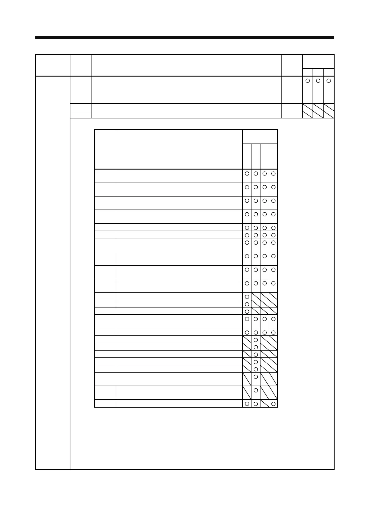
Table 5.8 Analog monitor setting value
Operation
mode (Note 1)
Setting
value
Item
Standard
Full.
Lin.
DD
00 (Linear) servo motor speed
(±8 V/max. speed)
01 Torque or thrust
(±8 V/max. torque or max. thrust) (Note 3)
02 (Linear) servo motor speed
(+8V/max. speed)
03 Torque or thrust
(+8 V/max. torque or max. thrust) (Note 3)
04 Current command (±8 V/max. current command)
05 Command pulse frequency (±10 V/±4 Mpulses/s)
06 Servo motor-side droop pulses (±10 V/100 pulses)
(Note 2)
07 Servo motor-side droop pulses (±10 V/1000 pulses)
(Note 2)
08 Servo motor-side droop pulses (±10 V/10000 pulses)
(Note 2)
09 Servo motor-side droop pulses (±10 V/100000 pulses)
(Note 2)
0A Feedback position (±10 V/1 Mpulse) (Note 2)
0B Feedback position (±10 V/10 Mpulses) (Note 2)
0C Feedback position (±10 V/100 Mpulses) (Note 2)
0D Bus voltage (200 V class: +8 V/400 V, 400 V class: +8
V/800 V)
0E Speed command 2 (±8 V/max. speed)
10 Load-side droop pulses (±10 V/100 pulses) (Note 2)
11 Load-side droop pulses (±10 V/1000 pulses) (Note 2)
12 Load-side droop pulses (±10 V/10000 pulses) (Note 2)
13 Load-side droop pulses (±10 V/100000 pulses) (Note 2)
14 Load-side droop pulses (±10 V/1 Mpulse) (Note 2)
15 Servo motor-side/load-side position deviation
(±10 V/100000 pulses)
16 Servo motor-side/load-side speed deviation
(±8 V/max. speed)
17 Encoder inside temperature (±10 V/±128 °C)
Note 1. Items with ○ are available for each operation mode.
Standard: Standard (semi closed loop system) use of the rotary servo motor
Full.: Fully closed loop system use of the rotary servo motor
Lin.: Linear servo motor use
DD: Direct drive (DD) motor use
2. Encoder pulse unit
3. 8 V is outputted at the maximum torque. However, when [Pr. PA11] and [Pr. PA12] are set to limit
torque, 8 V is outputted at the torque highly limited.
 Loading...

