5. PARAMETERS
5 - 39
Control
mode
No./symbol/
name
Setting
digit
Function
Initial
value
[unit]
P S T
PC15
MOD2
Analog
monitor 2
output
_ _ x x Analog monitor 2 output selection
Select a signal to output to MO2 (Analog monitor 2). Refer to appendix 8 (3) for
detection point of output selection.
Refer to [Pr. PC14] for settings.
01h
_ x _ _ For manufacturer setting 0h
x _ _ _ 0h
PC16
MBR
Electromagnetic
brake sequence
output
Set the delay time between MBR (Electromagnetic brake interlock) and the base
drive circuit is shut-off.
Setting range: 0 to 1000
0
[ms]
PC17
ZSP
Zero speed
Set the output range of ZSP (Zero speed detection).
ZSP (Zero speed detection) has hysteresis of 20 r/min or 20 mm/s.
Setting range: 0 to 10000
50
[r/min]/
[mm/s]
PC18
*BPS
Alarm history
clear
_ _ _ x Alarm history clear selection
Clear the alarm history.
0: Disabled
1: Enabled
When you select "Enabled", the alarm history will be cleared at next power-on. After
the alarm history is cleared, the setting is automatically disabled.
0h
_ _ x _ For manufacturer setting 0h
_ x _ _ 0h
x _ _ _ 0h
PC19
*ENRS
Encoder
output pulse
selection
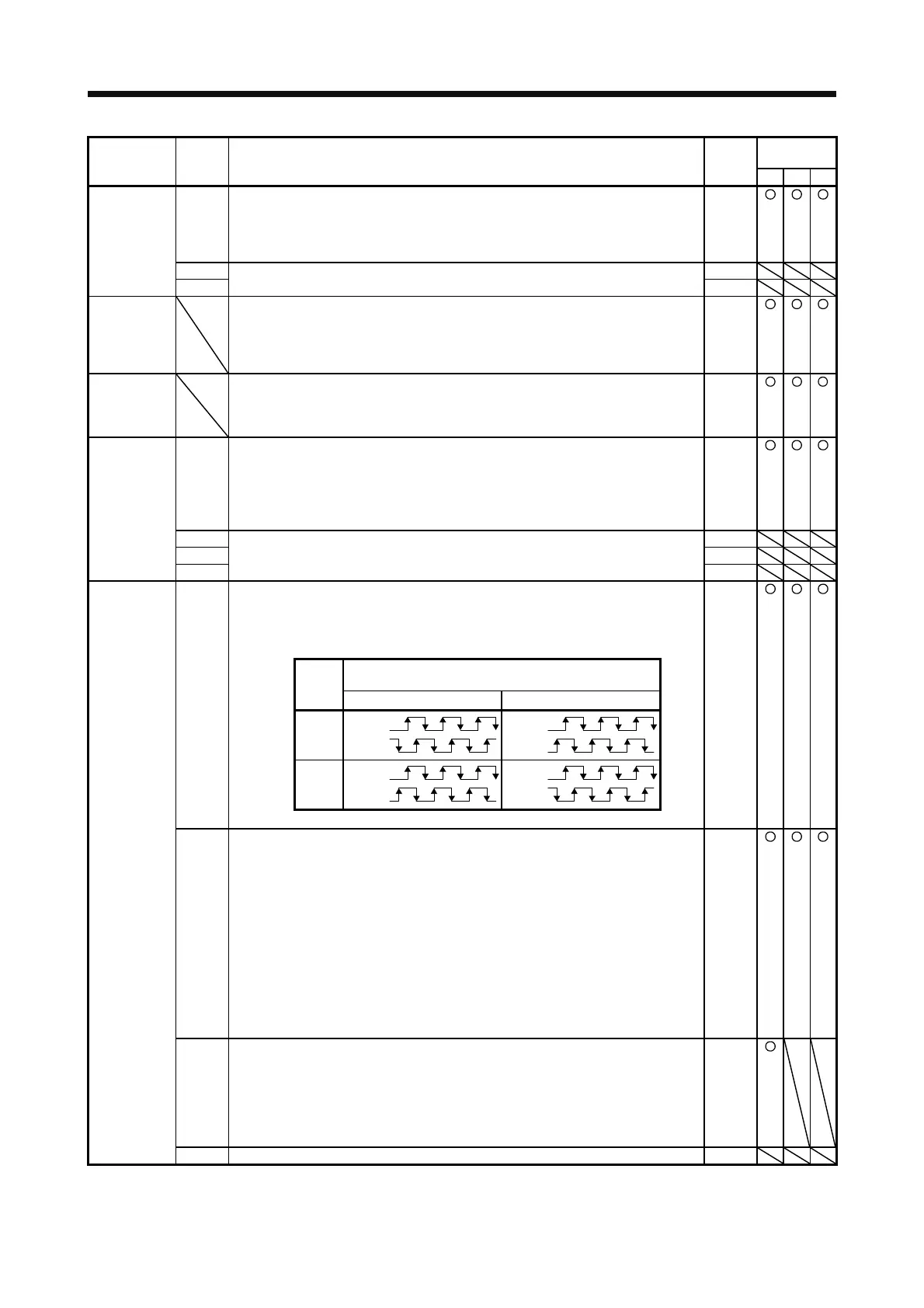
_ _ _ x Encoder output pulse phase selection
Select the encoder pulse direction.
0: A-phase 90° shift in CCW or positive direction
1: A-phase 90° shift in CW or negative direction
0h
Servo motor rotation direction/
linear servo motor travel direction
Setting
value
CCW or positive direction CW or negative direction
0
-phase
B-phase
-phase
B-phase
1
-phase
B-phase
-phase
B-phase
_ _ x _ Encoder output pulse setting selection
0: Output pulse setting
1: Dividing ratio setting
2: The same output pulse setting as the command pulse
3: A-phase/B-phase pulse electronic gear setting
4: A/B-phase pulse through output setting
When you select "1", the setting of [Pr. PA16 Encoder output pulses 2] will be
disabled. When you select "2", the settings of [Pr. PA15 Encoder output pulses] and
[Pr. PA16 Encoder output pulses 2] will be disabled. When you select the setting, do
not change the settings in [Pr. PA06] and [Pr. PA07] after the power-on.
Setting "4" will be enabled only when A/B/Z-phase differential output linear encoder is
used. And "Encoder output pulse phase selection (_ _ _ x)" will be disabled. When
another encoder is connected, [AL. 37 Parameter error] will occur. Setting "Standard
control mode (_ _ 0 _)" in [Pr. PA01] will trigger [AL. 37 Parameter error].
0h
_ x _ _ Selection of the encoders for encoder output pulse
Select an encoder for servo amplifier output.
0: Servo motor encoder
1: Load-side encoder
This is only for the fully closed loop system.
If "1" is set other than in the fully closed loop system, [AL. 37 Parameter error] will
occur.
0h
x _ _ _ For manufacturer setting 0h
 Loading...

