3. SIGNALS AND WIRING
3 - 36
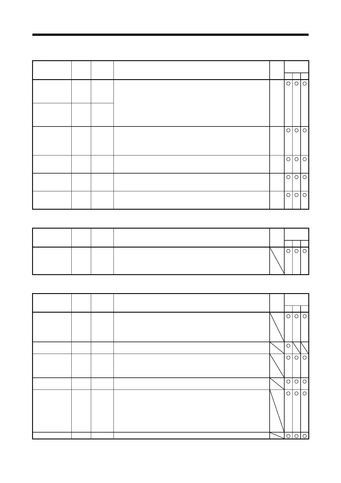
(3) Output signal
Control
mode
Device Symbol
Connector
pin No.
Function and application
I/O
division
PST
Encoder A-
phase pulse
(differential line
driver)
LA
LAR
CN1-4
CN1-5
DO-2
Encoder B-
phase pulse
(differential line
driver)
LB
LBR
CN1-6
CN1-7
The encoder output pulses set in [Pr. PA15] are outputted in the differential
line driver type.
In CCW rotation of the servo motor, the encoder B-phase pulse lags the
encoder A-phase pulse by a phase angle of π/2.
The relation between rotation direction and phase difference of the A-
phase and B-phase pulses can be changed with [Pr. PC19].
Encoder Z-
phase pulse
(differential line
driver)
LZ
LZR
CN1-8
CN1-9
The encoder zero-point signal is outputted in the differential line driver
type. One pulse is outputted per servo motor revolution. This turns on
when the zero-point position is reached. (negative logic)
The minimum pulse width is about 400 μs. For home position return using
this pulse, set the creep speed to 100 r/min. or less.
DO-2
Encoder Z-
phase pulse
(open-collector)
OP CN1-33 The encoder zero-point signal is outputted in the open-collector type. DO-2
Analog monitor 1 MO1 CN6-3 This is used to output the data set in [Pr. PC14] to between MO1 and LG in
terms of voltage.
Resolution: 10 bits or equivalent
Analog
output
Analog monitor 2 MO2 CN6-2 This signal outputs the data set in [Pr. PC15] to between MO2 and LG in
terms of voltage.
Resolution: 10 bits or equivalent
Analog
output
(4) Communication
Control
mode
Device Symbol
Connector
pin No.
Function and application
I/O
division
PST
RS-422 I/F SDP CN3-5 These are terminals for RS-422 communication.
SDN CN3-4
RDP CN3-3
RDN CN3-6
(5) Power supply
Control
mode
Device Symbol
Connector
pin No.
Function and application
I/O
division
PST
Digital I/F
power supply
input
DICOM CN1-20
CN1-21
Input 24 V DC (24 V DC ± 10% 500 mA) to I/O interface. The power supply
capacity changes depending on the number of I/O interface points to be
used.
For sink interface, connect + of 24 V DC external power supply.
For source interface, connect - of 24 V DC external power supply.
Open-collector
power input
OPC CN1-12 When inputting a pulse train in the open-collector type, supply this terminal
with the positive (+) power of 24 V DC.
Digital I/F
common
DOCOM CN1-46
CN1-47
Common terminal of input signal such as EM2 of the servo amplifier. This
is separated from LG.
For sink interface, connect - of 24 V DC external power supply.
For source interface, connect + of 24 V DC external power supply.
15 V DC power
supply
P15R CN1-1 This outputs 15 V DC to between P15R and LG. This is available as power
for TC, TLA, VC, or VLA. Permissible current: 30 mA
Control common LG CN1-3
CN1-28
CN1-30
CN1-34
CN3-1
CN3-7
CN6-1
This is a common terminal for TLA, TC, VC, VLA, FPA, FPB, OP ,MO1,
MO2, and P15R. Pins are connected internally.
Shield SD Plate Connect the external conductive portion of the shielded cable.
 Loading...
