14. COMMUNICATION FUNCTION
14 - 10
14.4 Command and data No. list
POINT
Even if a command or data No. is the same between different model servo
amplifiers, its description may differ.
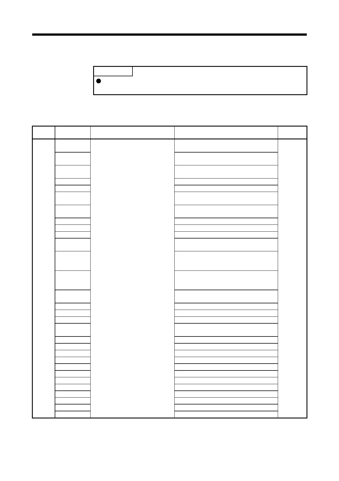
14.4.1 Reading command
(1) Status display (command [0] [1])
Command Data No. Description Status display
Frame
length
[0] [1] [0] [0] Status display symbol and unit Cumulative feedback pulses
Motor-side cumu. feedback pulses (after gear)
16
[0] [1] Servo motor speed
Servo motor speed
[0] [2] Droop pulses
Motor-side droop pulses
[0] [3] Cumulative command pulses
[0] [4] Command pulse frequency
[0] [5] Analog speed command voltage
Analog speed limit voltage
[0] [6] Analog torque limit voltage
Analog torque command voltage
[0] [7] Regenerative load ratio
[0] [8] Effective load ratio
[0] [9] Peak load ratio
[0] [A] Instantaneous torque
Instantaneous thrust
[0] [B] Position within one-revolution
Motor encoder position within one-revolution
Virtual position within one-revolution
[0] [C] ABS counter
Motor encoder ABS counter
Virtual ABS counter
[0] [D] Load to motor inertia ratio
Load to motor mass ratio
[0] [E] Bus voltage
[0] [F] Load-side cumulative feedback pulses
[1] [0] Load-side droop pulses
[1] [1] Load-side encoder information 1
Z-phase counter
[1] [2] Load-side encoder information 2
[1] [6] Temperature of motor thermistor
[1] [7] Motor-side cumu. feedback pulses (before gear)
[1] [8] Electrical angle
[1] [E] Motor-side/load-side position deviation
[1] [F] Motor-side/load-side speed deviation
[2] [0] Encoder inside temperature
[2] [1] Settling time
[2] [2] Oscillation detection frequency
[2] [3] Number of tough operations
[2] [8] Unit power consumption
[2] [9] Unit total power consumption
 Loading...
