5. PARAMETERS
5 - 51
Control
mode
No./symbol/
name
Setting
digit
Function
Initial
value
[unit]
P S T
PD32
*DOP3
Function
selection D-3
_ _ _ x CR (Clear) selection
Set CR (Clear).
0: Deleting droop pulses at the leading edge of turning on of CR
1: Continuous deleting of droop pulses while CR is on
0h
_ _ x _ For manufacturer setting 0h
_ x _ _ 0h
x _ _ _ 0h
PD34
*DOP5
Function
selection D-5
_ _ _ x Alarm code output
Select output status of alarm codes.
Alarm codes are outputted to the pins CN1-22, CN1-23, and CN1-24.
0: Disabled
1: Enabled
For details of the alarm codes, refer to chapter 8.
When "Enabled (absolute position detection system by DIO) (_ _ _ 1)" is selected in
[Pr. PA03] and when MBR (Electromagnetic brake interlock) or ALM (Malfunction) is
assigned to the CN1-22 pin, CN1-23 pin, or CN1-24 pin, selecting alarm code output
will generate [AL. Parameter error].
0h
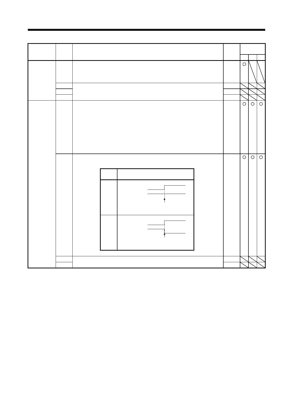
_ _ x _ Selection of output device at warning occurrence
Select ALM (Malfunction) output status at warning occurrence.
0h
Setting
value
Device status
0
OFF
ON
OFF
ON
WNG
LM
Warning occurrence
1
OFF
ON
OFF
ON
WNG
LM
Warning occurrence
_ x _ _ For manufacturer setting 0h
x _ _ _ 0h
 Loading...
