5. PARAMETERS
5 - 58
Control
mode
No./symbol/
name
Setting
digit
Function
Initial
value
[unit]
P S T
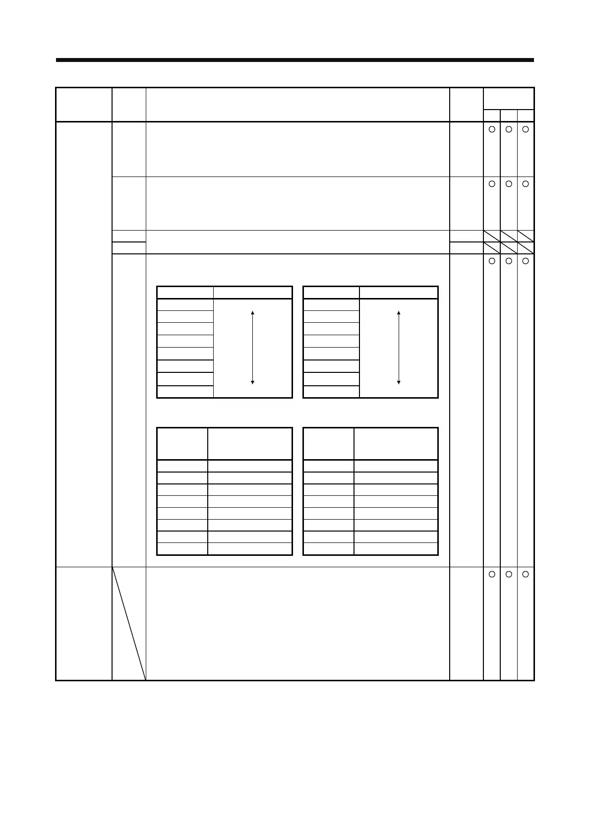
_ _ _ x Response selection
Set a response of the minute position detection method.
When reducing a travel distance at the magnetic pole detection, increase the setting
value.
Refer to table 5.11 for settings.
0h
_ _ x _ Load to motor mass ratio/load to motor inertia ratio selection
Select a load to mass of the linear servo motor primary-side ratio or load to mass of
the direct drive motor inertia ratio used at the minute position detection method. Set
a closest value to the actual load.
Refer to table 5.12 for settings.
0h
_ x _ _ For manufacturer setting 0h
PL17
LTSTS
Magnetic pole
detection -
Minute
position
detection
method -
Function
selection
x _ _ _ 0h
Table 5.11 Response of minute position detection method at
magnetic pole detection
Setting value Response Setting value Response
0 Low response 8 Middle response
1 9
2 A
3 B
4 C
5 D
6
E
7 Middle response F High response
Table 5.12 Load to motor mass ratio/load to motor inertia ratio
Setting
value
Load to motor mass
ratio/load to motor
inertia ratio
Setting
value
Load to motor mass
ratio/load to motor
inertia ratio
0 10 times or less 8 80 times
1 10 times 9 90 times
2 20 times A 100 times
3 30 times B 110 times
4 40 times C 120 times
5 50 times D 130 times
6 60 times E 140 times
7 70 times F 150 times or more
PL18
IDLV
Magnetic pole
detection -
Minute
position
detection
method -
Identification
signal
amplitude
Set an identification signal amplitude used in the minute position detection method.
This parameter is enabled only when the magnetic pole detection is the minute
position detection method.
Setting "0" will be 100% amplitude.
Setting range: 0 to 100
0
[%]
 Loading...
