1. FUNCTIONS AND CONFIGURATION
1 - 11
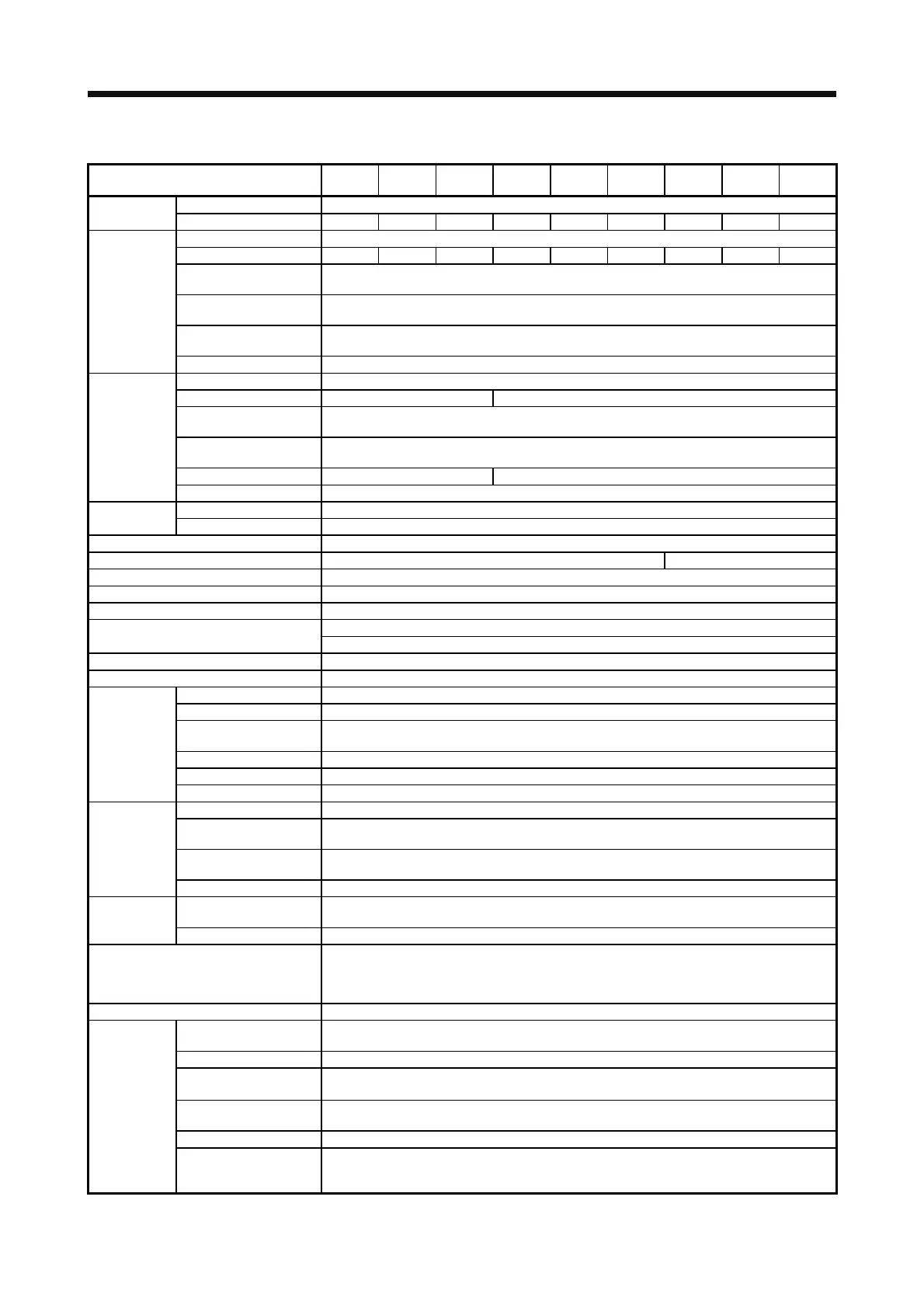
(2) 400 V class
Model: MR-J4-
60A4
(-RJ)
100A4
(-RJ)
200A4
(-RJ)
350A4
(-RJ)
500A4
(-RJ)
700A4
(-RJ)
11KA4
(-RJ)
15KA4
(-RJ)
22KA4
(-RJ)
Rated voltage 3-phase 323 V AC
Output
Rated current [A] 1.5 2.8 5.4 8.6 14.0 17.0 32.0 41.0 63.0
Voltage/Frequency 3-phase 380 V AC to 480 V AC, 50 Hz/60 Hz
Rated current [A] 1.4 2.5 5.1 7.9 10.8 14.4 23.1 31.8 47.6
Permissible voltage
fluctuation
3-phase 323 V AC to 528 V AC
Permissible frequency
fluctuation
Within ±5%
Power supply
capacity
[kVA] Refer to section 10.2.
Main circuit
power supply
input
Inrush current [A] Refer to section 10.5.
Voltage/Frequency 1-phase 380 V AC to 480 V AC, 50 Hz/60 Hz
Rated current [A] 0.1 0.2
Permissible voltage
fluctuation
1-phase 323 V AC to 528 V AC
Control circuit
power supply
input
Permissible frequency
fluctuation
Within ±5%
Power consumption [W] 30 45
Inrush current [A] Refer to section 10.5.
Voltage 24 V DC ± 10%
Interface power
supply
Current capacity [A] (Note 1) 0.5 (including CN8 connector signals)
Control method Sine-wave PWM control, current control method
Dynamic brake Built-in External option (Note 6)
Fully closed loop control Compatible
Scale measurement function Not compatible
Load-side encoder interface (Note 5) Mitsubishi high-speed serial communication
USB: connection to a personal computer or others (MR Configurator2-compatible)
Communication function
RS-422: 1 : n communication (up to 32 axes)
Encoder output pulses Compatible (A/B/Z-phase pulse)
Analog monitor Two channels
Max. input pulse frequency 4 Mpulses/s (for differential receiver) (Note 4), 200 kpulses/s (for open collector)
Positioning feedback pulse Encoder resolution (resolution per servo motor revolution): 22 bits
Command pulse multiplying
factor
Electronic gear A:1 to 16777215, B:1 to 16777215, 1/10 < A/B < 4000
In-position range setting 0 pulse to ±65535 pulses (command pulse unit)
Error excessive ±3 revolutions
Position control
mode
Torque limit Set by parameter setting or external analog input (0 V DC to +10 V DC/maximum torque)
Speed control range Analog speed command 1: 2000, internal speed command 1: 5000
Analog speed command
input
0 to ±10 V DC/rated speed (The speed at 10 V is changeable with [Pr. PC12].)
Speed fluctuation ratio
±0.01% or less (load fluctuation 0 % to 100%), 0% (power fluctuation ±10%), ±0.2% or less (ambient
temperature 25 ± 10 °C) when using analog speed command
Speed control
mode
Torque limit Set by parameter setting or external analog input (0 V DC to +10 V DC/maximum torque)
Analog torque command
input
0 V DC to ±8 V DC/maximum torque (input impedance 10 kΩ to 12 kΩ )
Torque control
mode
Speed limit Set by parameter setting or external analog input (0 V DC to 10 V DC/rated speed)
Protective functions
Overcurrent shut-off, regenerative overvoltage shut-off, overload shut-off (electronic thermal), servo
motor overheat protection, encoder error protection, regenerative error protection, undervoltage
protection, instantaneous power failure protection, overspeed protection, error excessive protection,
magnetic pole detection protection, and linear servo control fault protection
Functional safety STO (IEC/EN 61800-5-2)
Standards certified by CB
EN ISO 13849-1 category 3 PL d, IEC 61508 SIL 2, EN 62061 SIL CL 2,
and EN 61800-5-2 SIL 2
Response performance 8 ms or less (STO input off → energy shut off)
(Note 2)
Test pulse input (STO)
Test pulse interval: 1 Hz to 25 Hz
Test pulse off time: Up to 1 ms
Mean time to dangerous
failure (MTTFd)
100 years or longer
Safety
performance
Diagnosis coverage (DC) Medium (90% to 99%)
Average probability of
dangerous failures per hour
(PFH)
1.68 × 10
-10
[1/h]
 Loading...
