EasyManuals Logo

Mitsubishi MR-J4-70A User Manual

Mitsubishi MR-J4-70A
640 pages
To Next Page IconTo Next Page
To Previous Page IconTo Previous Page
Page #399 background imageLoading...
Page #399 background image
11. OPTIONS AND AUXILIARY EQUIPMENT
11 - 68
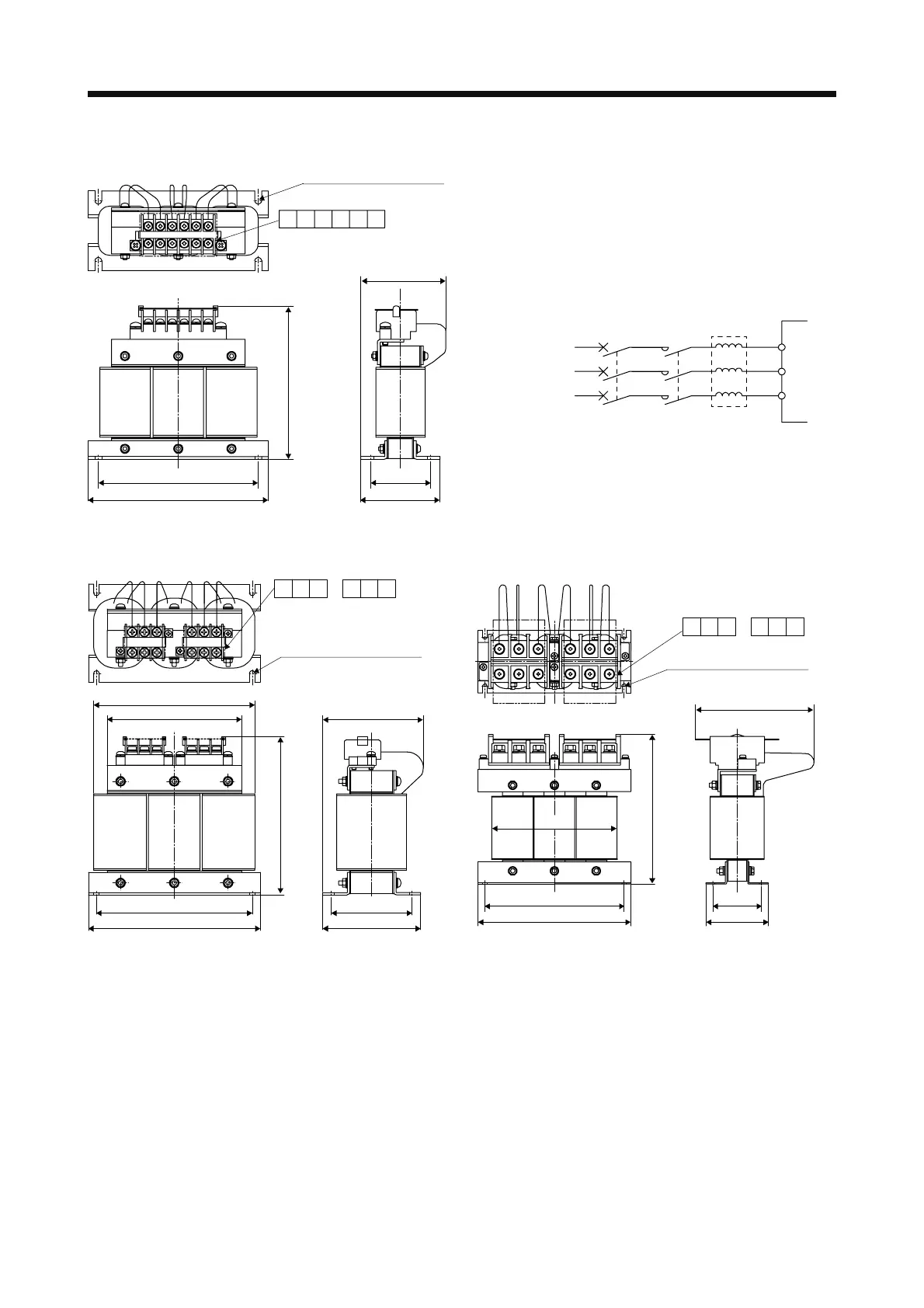
(2) 400 V class
W ± 0.5
W1
RX ZSYT
H ± 5
D1
D2
4-d mounting hole (Note)
(φ5 groove)
D or less
Fig. 11.10
Y
Z
S
T
MCMCCB
FR-HAL-H
Servo amplifie
r
3-phase
400 V class
XR
L1
L2
L3
3-phase
380 V AC to
480 V AC
W ± 0.5
W1
D1
D2
H ± 5
125 D or less
150
4-d mounting hole (Note)
ZYTRXS
(φ6 groove)
Fig. 11.11
D or less
4-d mounting hole (Note)
ZYTRXS
H ± 5
180
W ± 0.5
W1
D1
D2
(φ8 groove)
Fig. 11.12
Note. Use this for grounding.

Table of Contents

Questions and Answers:

Question and Answer IconNeed help?

Do you have a question about the Mitsubishi MR-J4-70A and is the answer not in the manual?

Mitsubishi MR-J4-70A Specifications

General IconGeneral
BrandMitsubishi
ModelMR-J4-70A
CategoryAmplifier
LanguageEnglish

Related product manuals