11. OPTIONS AND AUXILIARY EQUIPMENT
11 - 85
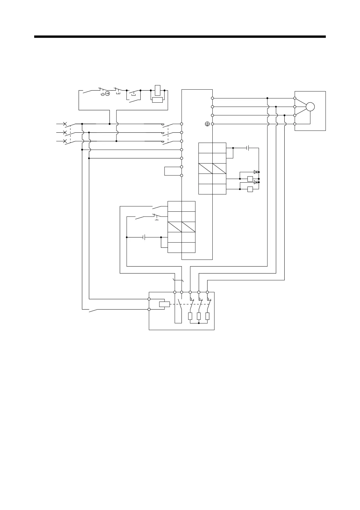
(2) Connection example
(a) 200 V class
UV
46
DOCOM
(Note 3)
MC
1314 W
External dynamic brake
a
b
RA2
L11
L21
P3
P4
Servo amplifier
L3
L2
L1
U
V
W
U
V
W
E
M
Servo motor
Operation read
CN1
MCCB
MC
ALM
RA1
OFF ON
MC
EMG stop switch
Dynamick brake
interlock
SK
(Note 2)
Power
supply
(Note 1) DB
48 ALM
47
DOCOM
24 V DC (Note 5)
RA1
RA2
24 V DC
(Note 5)
(Note 4)
Main circuit
power supply
15SON
42
20
21
EM2
CN1
(Note 6)
DICOM
DICOM
Note 1. Assign DB (Dynamic brake interlock) in [Pr. PD23] to [Pr. PD26] and [Pr. PD28].
2. Refer to section 1.3 for the power supply specifications.
3. Depending on the main circuit voltage and operation pattern, bus voltage decreases, and that may cause the forced stop
deceleration to shift to the dynamic brake deceleration. When dynamic brake deceleration is not required, slow the time to turn
off the magnetic contactor.
4. Turn off EM2 when the main power circuit power supply is off.
5. The illustration of the 24 V DC power supply is divided between input signal and output signal for convenience. However, they
can be configured by one.
6. Between P3 and P4 is connected by default. When using the power factor improving DC reactor, remove the short bar
between P3 and P4. Refer to section 11.11 for details. Additionally, a power factor improving DC reactor and power factor
improving AC reactor cannot be used simultaneously.
 Loading...
