14. COMMUNICATION FUNCTION
14 - 17
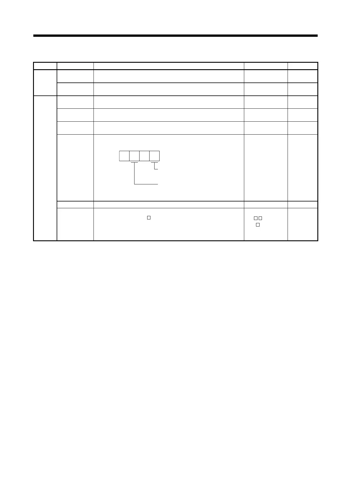
(8) Test operation mode data (command [9] [2], [A] [0])
Command Data No. Description Setting range Frame length
[0] [0] Input signal for test operation Refer to section
14.5.7.
8 [9] [2]
[A] [0] Forced output of signal pin Refer to section
14.5.9.
8
[1] [0] Writes the servo motor speed in the test operation mode (JOG
operation and positioning operation).
0000 to 7FFF 4
[1] [1] Writes the acceleration/deceleration time constant in the test
operation mode (JOG operation and positioning operation).
00000000 to
7FFFFFFF
8
[2] [0] Sets the travel distance in the test operation mode (Positioning
operation).
00000000 to
7FFFFFFF
8
[2] [1] Selects the positioning direction of test operation (positioning
operation).
0: Forward rotation direction
1: Reverse rotation direction
0: Command pulse unit
1: Encoder pulse unit
00
0000 to 0101 4
[A] [0]
[4] [0] This is a start command for test operation (positioning operation). 1EA5 4
[4] [1] This is used to make a temporary stop during test operation
(positioning operation). "
" in the data indicates a blank.
STOP: Temporary stop
GO□□: Restart for remaining distance
CLR□: Remaining distance clear
STOP
GO
CLR
4
 Loading...
