27
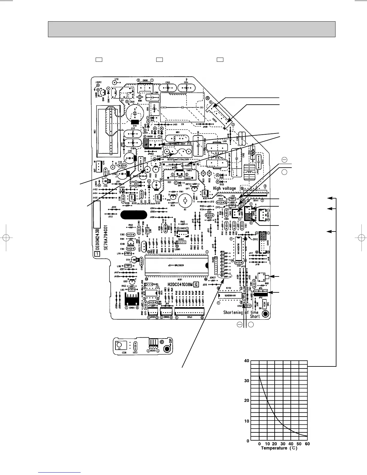
TEST POINT DIAGRAM AND VOLTAGE
MSH-A18WV - MSH-A24WV - MSH-A30WV -
Indoor electronic control P.C. board
E1E1E1
Fan motor power supply
Fuse (F11)
250V AC 3.15A
}
Power supply input
230V AC
+
}
5V DC
Indoor coil
thermistor(RT12(main))
Timer short mode point
(JPS, JPG)
(Refer to page 18.)
Emergency operation
switch
+
}
12V DC
Indoor coil thermistor(RT12(main), RT13(sub))
Room temperature thermistor (RT11)
Resistance(k")
Room temperature ther-
mistor(RT11)
Release of “Auto restart function”
Solder jumper wire to JR07.
(Refer to page 19.)
MSH-A30WV
Indoor coil
thermistor(RT13(sub))
R132
Receiver P.C. board
OB321-1.qxp 03.11.13 4:03 PM Page 27
 Loading...