EasyManua.ls Logo

Mitsubishi MSH-A30WV User Manual

Mitsubishi MSH-A30WV
32 pages
To Next Page IconTo Next Page
Page #1 background imageLoading...
Page #1 background image
SERVICE MANUAL
CONTENTS
1. TECHNICAL CHANGES ····································2
2. PART NAMES AND FUNCTIONS······················2
3. SPECIFICATION·················································4
4. NOISE CRITERIA CURVES·······························5
5. OUTLINES AND DIMENSIONS ·························6
6. WIRING DIAGRAM ············································7
7. REFRIGERANT SYSTEM DIAGRAM················8
8. MICROPROCESSOR CONTROL ······················9
9. SERVICE FUNCTIONS ····································18
10. TROUBLESHOOTING······································20
11. DISASSEMBLY INSTRUCTIONS·····················28
12. PARTS LIST······················································30
13. OPTIONAL PARTS ······················BACK COVER
Wireless type
Models
MSH-A18WV -
(
WH
)
MSH-A24WV -
(
WH
)
MSH-A30WV -
(
WH
)
E1
E1
E1
No. OB321
SPLIT-TYPE, HEAT PUMP AIR CONDITIONERS
MSH-A18WV -
MSH-A24WV -
MSH-A30WV -
E1
E1
E1
NOTE:
This service manual describes technical data of the indoor unit.
•Refer to the service manual OB322 when MSH-A18WV- , MSH-A24WV- or MSH-A30WV- is
connected with MUH-A18WV- , MUH-A24WV- or MUH-A30WV- .
•Refer to the service manual OB319 when MSH-A18WV- is connected with MXZ-A18WV- ,
MXZ-A26WV- or MXZ-A32WV- as multi system units.
•Refer to the service manual OB319 when MSH-A24WV- is connected with MXZ-A26WV- or
MXZ-A32WV- as multi system units.
E1
E1E1
E1E1
E1E1
E1E1E1
E1E1E1
Indication of model name
OB321-1.qxp 03.11.13 4:03 PM Page 1
Question and Answer IconNeed help?

Do you have a question about the Mitsubishi MSH-A30WV and is the answer not in the manual?

Mitsubishi MSH-A30WV Specifications

General IconGeneral
BrandMitsubishi
ModelMSH-A30WV
CategoryAir Conditioner
LanguageEnglish

Summary

Part Names and Functions

Indoor Unit Components

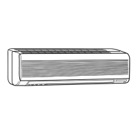
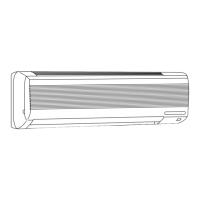
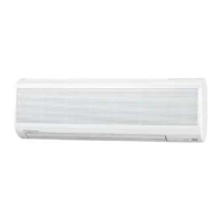
Identifies and describes the components of the indoor unit, including filters, vanes, and controls.

Remote Controller Operation

Remote Controller Display and Buttons

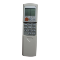
Details the operational display, indicator lamps, and key buttons on the wireless remote controller.

Technical Specifications

Outline and Dimensions

Indoor Unit Dimensions and Piping

Provides detailed dimensions for the indoor unit and specifications for refrigerant pipe and drain hose sizes.

Wiring Diagrams

Wiring Diagram: MSH-A18/A24WV Indoor Unit

Illustrates the internal electrical connections and component layout for MSH-A18WV and MSH-A24WV indoor units.

Wiring Diagram: MSH-A30WV Indoor Unit

Details the electrical wiring and component connections for the MSH-A30WV indoor unit.

Refrigerant System Diagrams

Refrigerant Diagram: MSH-A18WV

Illustrates the refrigerant circuit and component flow for the MSH-A18WV indoor unit.

Refrigerant Diagram: MSH-A24WV

Shows the refrigerant flow paths and connections within the MSH-A24WV indoor unit.

Refrigerant Diagram: MSH-A30WV

Details the refrigerant circuit and component arrangement for the MSH-A30WV indoor unit.

Microprocessor Control System

Remote Controller Interface

Explains the layout and functions of the wireless remote controller for system operation.

Standard Cool Operation

Standard Dry Operation

Standard Heat Operation

Timer Operations

Setting On/Off Timers

Provides instructions on how to set the ON-TIMER and OFF-TIMER for the air conditioner.

Emergency and Test Operation

Service Functions

PC Board Modification for Individual Operation

Instructions on modifying the PC board to assign individual remote controllers to specific indoor units.

Troubleshooting Guide

Troubleshooting Precautions

Lists important safety and preliminary checks to perform before starting troubleshooting procedures.

Troubleshooting Procedure Overview

Outlines the general steps for diagnosing abnormalities using the operation indicator lamp and checks.

Troubleshooting Flowchart

Troubleshooting: Mis-wiring and Power Issues

Diagnoses issues related to mis-wiring, poor contact, or wire disconnection indicated by specific flash patterns.

Troubleshooting: Control System and Outdoor Unit Faults

Addresses issues with the indoor control system, outdoor power system, thermistors, and refrigerant system.

Troubleshooting Check Table

Troubleshooting: Mis-Wiring and Power System Faults

Details symptoms, detection methods, and checks for mis-wiring and outdoor power system issues.

Troubleshooting: Outdoor Unit and System Faults

Addresses issues with outdoor thermistors, control systems, refrigerant systems, and operation mode settings.

Main Parts Trouble Criteria

Room Temperature Thermistor (RT11) Check

Provides resistance measurement criteria for the room temperature thermistor (RT11) to check for abnormalities.

Troubleshooting: Indoor Fan Motor

Troubleshooting: Remote Controller and Receiver

Troubleshooting: Indoor Electronic Control PC Board

Troubleshooting: Checking for Mis-wiring

Test Point Diagram and Voltages

Disassembly Instructions

Removing the Electrical Box

Removing the Vane Motor

Removing Fan Motor and Heat Exchanger

Parts List

Indoor Unit Functional and Electrical Parts

Related product manuals