EasyManua.ls Logo

Mitsubishi MUZ-A15NA User Manual

Mitsubishi MUZ-A15NA
79 pages
To Next Page IconTo Next Page
Page #1 background imageLoading...
Page #1 background image
SERVICE MANUAL
CONTENTS
1. TECHNICAL CHANGES ····································2
2. PART NAMES AND FUNCTIONS······················5
3. SPECIFICATION·················································6
4. OUTLINES AND DIMENSIONS ·······················10
5. WIRING DIAGRAM···········································11
6. REFRIGERANT SYSTEM DIAGRAM··············15
7. DATA·································································17
8. ACTUATOR CONTROL····································30
9. SERVICE FUNCTIONS ····································31
10. TROUBLESHOOTING······································31
11. DISASSEMBLY INSTRUCTIONS·····················59
12. PARTS LIST······················································66
12-1. PARTS LIST·············································66
12-2. RoHS PARTS LIST··································72
13. OPTIONAL PARTS ·························BACK PAGE
Wireless type
Models
MUZ-A09NA MUZ-A09NA-
MUZ-A12NA MUZ-A12NA-
MUZ-A15NA MUZ-A15NA-
MUZ-A17NA MUZ-A17NA-
MUZ-A24NA MUZ-A24NA-
MUY-A15NA
MUY-A17NA
MUY-A24NA
U1
U1
U1
U1
U1
No. OB451
SPLIT-TYPE, HEAT PUMP AIR CONDITIONERS
OUTDOOR UNIT
Indoor unit service manual
MSZ-A•NA Series (OB450)
MUZ-A09NA MUY-A15NA
MUZ-A12NA MUY-A17NA
MUZ-A15NA
NOTE:
This service manual describes technical data of the outdoor units.
RoHS compliant products have <G> mark on the spec name plate.
For servicing of RoHS compliant products, refer to the PARTS
LIST (RoHS compliant).
TM
HFC
utilized
R410A
OB451--1.qxp 06.3.29 9:51 AM Page 1
Question and Answer IconNeed help?

Do you have a question about the Mitsubishi MUZ-A15NA and is the answer not in the manual?
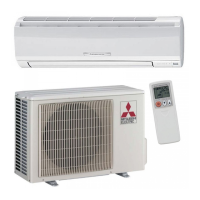
Mitsubishi MUZ-A15NA Specifications

General IconGeneral
RefrigerantR410A
Cooling Capacity (kW)4.4 kW
Heating Capacity (kW)4.7 kW
Cooling Capacity15000 BTU/h
Heating Capacity16000 BTU/h
Voltage208/230V
Power Supply208/230V, 1 phase, 60Hz

Summary

Technical Changes

Part Names and Functions

Specifications

Outlines and Dimensions

Wiring Diagram

Refrigerant System Diagram

Data and Performance

Performance Data

Presents cooling and heating capacities under various operational conditions.

Condensing Pressure Charts

Graphs illustrating pressure relationships based on ambient and indoor conditions.

Standard Operation Data

Details key technical parameters during standard operating conditions.

Operating Range Guidelines

Specifies voltage and temperature limits for reliable unit operation.

Inverter Frequency Correction Factors

Graphs showing inverter frequency impact on capacity and input.

Test Run Operation Procedure

Instructions for performing fixed-frequency operational tests.

Actuator Control

Outdoor Fan Motor Control Logic

Details the fan motor's operation relative to the compressor.

Reversing Valve Coil Control

Explains the operation of the reversing valve coil in different modes.

Sensor and Actuator Relationships

Maps sensors to their corresponding controlled actuators.

Service Functions

Defrost Setting Adjustment

Procedure to modify the defrost finish temperature via jumper wire.

Troubleshooting and Error Diagnosis

Troubleshooting Cautions

Important safety and procedural advice before starting diagnosis.

Failure Mode Recall Function

Procedure to retrieve and display stored error codes for diagnosis.

Troubleshooting Check Table

Lists symptoms, LED indications, conditions, and corrective actions.

Trouble Criterion for Main Parts

Provides resistance and measurement criteria for key components.

Comprehensive Troubleshooting Flows

Detailed step-by-step diagnostic guides for common operational issues.

Test Point Diagrams and Voltages

Visual guides for measuring electrical signals on various P.C. boards.

Disassembly and Component Removal

Cabinet and Panel Removal

Procedures for removing the service panel, top panel, valve cover, and cabinet.

Inverter and P.C. Board Removal

Steps to access and remove the inverter assembly and P.C. boards.

R.V. Coil Removal

Procedure for removing the reversing valve coil.

Thermistor Removal Procedures

Steps to remove temperature sensors from their holders.

Outdoor Fan Motor Removal

Procedure for removing the outdoor fan motor.

Compressor and 4-way Valve Removal

Steps to remove the compressor and 4-way valve.

Reactor Removal

Procedure for removing the reactor component.

Parts List

Structural and Functional Parts (non-RoHS)

List of mechanical components for non-RoHS compliant units.

Electrical Parts (non-RoHS)

List of electronic and electrical components for non-RoHS compliant units.

Structural and Functional Parts (RoHS)

List of mechanical components for RoHS compliant units.

Electrical Parts (RoHS)

List of electronic and electrical components for RoHS compliant units.

Optional Parts

Drain Socket Information

Details on the drain socket accessory for specific models.

Drain Socket Assembly

Information regarding the drain socket assembly.

Related product manuals