En-5
Fig. 1 Fig.2
Fig.3 Fig.4
Fig.5 Fig.6
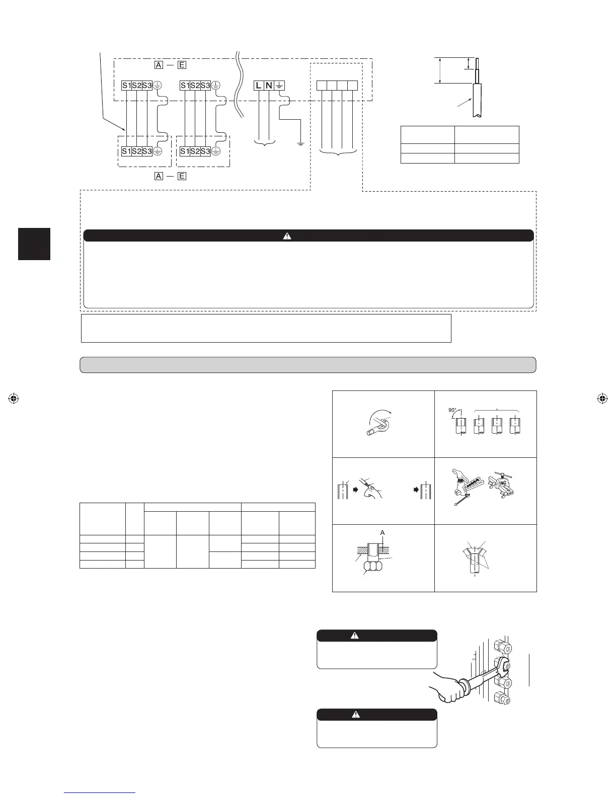
3-1. FLARING WORK
Pipediameter
(mm)
Nut
(mm)
A(mm) Tighteningtorque
Clutch
typetool
forR410A
Clutch
typetool
forR22
Wing nut
typetool
forR22
N•m kgf•cm
ø6.35(1/4”) 17
0to0.5 1.0to1.5
1.5to2.0
13.7to17.7 140to180
ø9.52(3/8”) 22 34.3to41.2 350to420
ø12.7(1/2”) 26
2.0to2.5
49.0to56.4 500to575
ø15.88(5/8”) 29 73.5to78.4 750to800
TiltedUnevenBurred
Good
No good
Burr
Copperpipe
Sparereamer
Pipecutter
Smooth all
around
Evenlength
all around
Inside is shin-
ingwithoutany
scratches.
Flare nut
Die
Copperpipe
Clutchtype
Flaring tool
Wingnuttype
3-2. PIPE CONNECTION
1)Applyathincoatofrefrigerationoil(G)tothearedendsofthepipesand
thepipeconnectionsoftheoutdoorunit.Donotapplyrefrigerationoilon
screwthreads.Excessivetighteningtorquewillresultindamageonthe
screw.
2)Alignthecenterofthepipewiththatofthepipeconnectionsoftheoutdoor
unit,thenhandtightenthearenut3to4turns.
3)Tightenthearenutwithatorquewrenchasspeciedinthetable.
•Over-tighteningmaycausedamagetothearenut,resultinginrefriger-
antleakage.
•Besuretowrapinsulationaroundthepiping.Directcontactwiththebare
pipingmayresultinburnsorfrostbite.
3-3. INSULATION AND TAPING
1)Coverpipingjointswithpipecover.
2)Foroutdoorunitside,surelyinsulateeverypipingincludingvalves.
3)Usingpipingtape(E),applytapingstartingfromtheentryofoutdoorunit.
• Stoptheendofpipingtape(E)withtape(withadhesiveagentattached).
• Whenpipinghavetobearrangedthroughaboveceiling,closetorwhere
thetemperatureandhumidityarehigh,windadditionalcommerciallysold
insulationtopreventcondensation.
Copper
pipe
1)Cutthecopperpipecorrectlywithpipecutter.(Fig.1,2)
2)Completelyremoveallburrsfromthecutcrosssectionofpipe.(Fig.3)
• Aimthecopperpipedownwardwhileremovingburrstopreventburrs
fromdroppinginthepipe.
3)Removearenutsattachedtoindoorandoutdoorunits,thenputthem
onpipehavingcompletedburrremoval.(Notpossibletoputthemon
afteraringwork.)
4)Flaringwork(Fig.4,5).Firmlyholdcopperpipeinthedimensionshown
in the table. Select A mm from the table according to the tool selected.
5)Check
• ComparethearedworkwithFig.6.
• Ifareisnotedtobedefective,cutoffthearedsectionanddoaring
workagain.
WARNING
When installing the unit, securely
connect the refrigerant pipes before
starting the compressor.
CAUTION
When there are the ports which are
not used, make sure their nuts are
tightened securely.
3. FLARING WORK AND PIPE CONNECTION
• Besuretoattacheachscrewtoitscorrespondentterminalwhensecuringthecordand/orthewiretotheterminalblock.
• Makeearthwirealittlelongerthanothers.(Morethan35mm)
• Forfutureservicing,giveextralengthtotheconnectingwires.
<OUTDOORUNIT>
Indoor/outdoorunit
connectingwire
<INDOORUNIT>
Terminalblock
POWERSUPPLY
~/N230V50Hz
Terminalblock Terminalblock
Terminalblockfor
powersupply
Terminalblock
ThisunithasdemandresponsecapabilitywhichiscompliantwithAS/NZS4755.3.1.Toactivatethisfunction,youneedtomakeacontractwithremote
agentssuchaselectricsupplycompany,thenthisunitshouldbeconnectedtoDemandresponseenablingdevise(DRED).Forfurtherinformation,
consultyourdealer.Thisunitsupports3DemandResponseModes(DRMs):DRM1,DRM2andDRM3.
CAUTION
•Topreventmalfunctioncausedbynoise,routethecordconnectingthisunittoDREDandthepowersupplycordasparallelaspossible.
•Donotconnectthedemandcontroltransmissioncabletotheterminalblockforpowersupply.
•Donotpull,extremelybendorapplystrongpressureonthewiretopreventfailure.
•DonotscrewDREDtooutdoorunit.
•DonotputDREDinoutdoorunit.
•Secureelectricalwiringaboveclamp.
•DonotgetDREDwirecaughtintheservicepanel.
1:DRM1
2:DRM2
3:DRM3
C:COMMON
AS/NZS4755
terminalblock
35mm
15mm
Leadwire
Model
INDOOR/
OUTDOORUNIT
MXZ-5E100VAD
A
–
E
MXZ-4E80VAD
A
–
D
WG79A696H02_en.indd 5 2016/04/21 14:46:39
 Loading...