9-2
Chapter 9 Brakes
Torque specifications
Ft-lbs (unless otherwise indicated)
Brake caliper mounting bolts
S~liding caliper .......................................
51 to 65
Floating caliper
-Upper mounting bolt ................................
29 to 36
Lower mounting bolt
................................ 23 to 30
Caliper mounting bracket bolts
2WDmodels ........................................
51 to65
4WDmodels
........................................
58 to 72
Caliper inlet fitting .....................................
120 to 144 in-lbs
Disc-to-hub bolts
2WD ..............................................
36
4WD ..............................................
36to44 II
-.
Wheel cylinder mounting bolts
............................
13to15
Master cylinder mounting nuts
............................ 72 to 108.in-lbs
Power brake booster mounting nuts
....................... 72 to 108 in-lbs
Wheellugnuts ........................................
See Chapter I
1
General information
The vehicles covered by this manual are equipped with hydraulically
operated front and rear brake systems. The front brakes are disc-type.
Earlier models use a sliding caliper while later models use a floating cali-
per.
The rear brakes on all models are drum-type. Earlier models use a
duo-servo type rear brake while later models are equipped with leading/
trailing type.
These models are equipped with a dual master cylinder which allows
the operation of half of the system if the other half fails. This system also
incorporates a blend proportioning valve which limits pressure to the rear
brakes under heavy braking to prevent rear wheel lock-up. Later models
have a Load Sensing Proportioning Valve (LSPV) mounted to the frame
and connected to the rear axle by a link.
All models are equipped with a power brake boosterwhich utilizes en-
ginevacuum to assist in application of the brakes. The parking brakeoper-
ates the rear brakes only, through cable actuation.
There are some notes and cautions involving the brake system on this
vehicle:
a) Use only DOT 3 brake fluid in this system.
b) The brake pads and linings contain asbestos fibers which are haz-
ardous fo your health if inhaled. Whenever you work on the brake
system components, carefully clean all parts with brake cleaner.
Do not allow the fine asbestos dust to become airborne.
c) Safety should be paramount whenever any servicing of the brake
components is performed. Do not use parts or fasteners which are
not in perfect condition, and be sure that all clearances and torque
specifications are adhered to. If you are at all unsure about a certain
~~ procedge, seek professional advice. Upon completion of any
brake system work, test the brakes carefully in a controlled area be-
fore putting the vehicle into normal service. If a problem is sus-
~_ p~ected~in the brake system, do not drive the vehicle until the fault
is corrected.
d) Tires, load and front end alignment are factors which also affect
brakingperformance.
2 Disc brake pads - replacement
Warning: Disc brake pads must be replaced on both front wheels at the
s?ime tfme - never replace the pads on only one wheel. Also, the dust
created by the brake system may contain asbestos, whxh is harmful to
your health. Never blow it out with compressedairand don’t inhale any of
KAn approved filtering mask should be worn when working on the brakes.
Do not, under any circumstances, use petroleum-based solvents to clean
brake parts. Use brake cleaner or denatured alcohol on/y!
Note 1: When servicing the disc brakes, use only high-quality, nati&ally
recognized name brand pads.
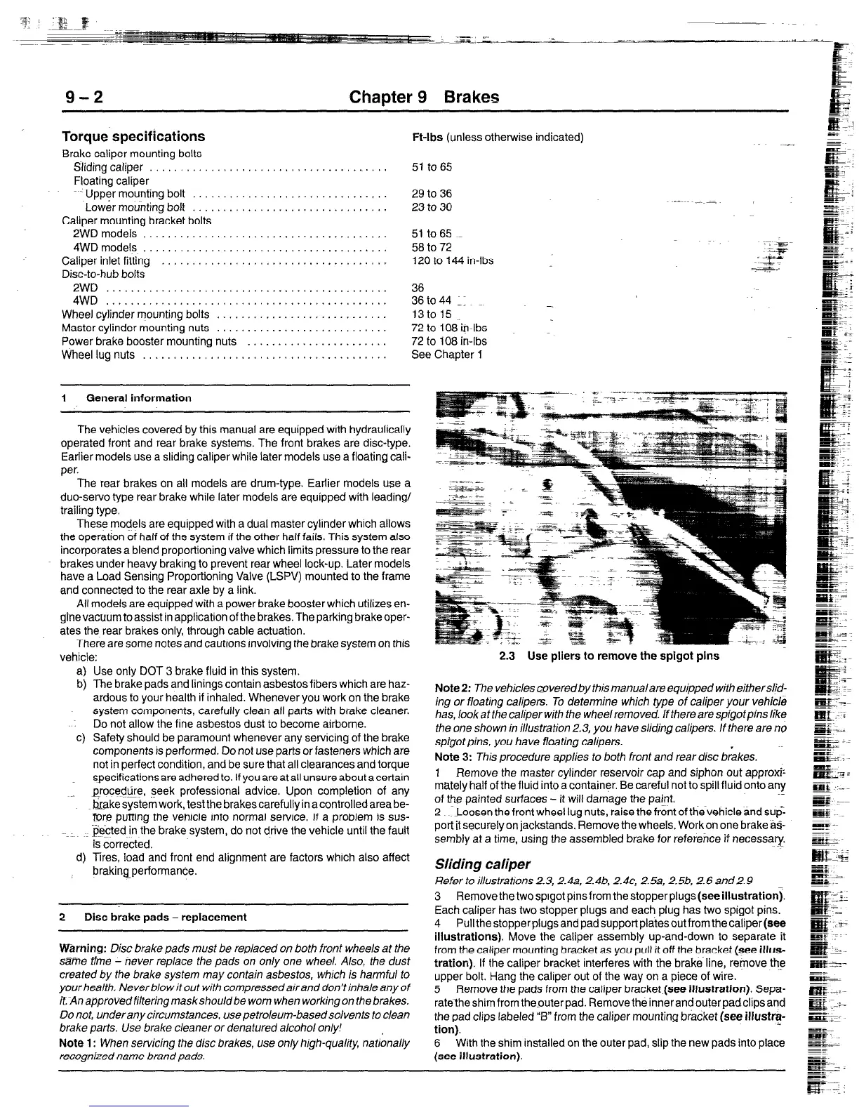
2.3 Use pliers to remove the spigot pins
Note 2: The vehicles covered by this manual are equipped with eitherslid-
ing or ffoating calipers. To determine which type of caliper your vehicle
has, look at the caliper with the wheel removed. Ifthere are spigofpins like
the one shown in illustration 2.3, you have sliding calipers. If there are no
spigot pins, you have floating calipers.
Note 3: This procedure applies to both front and rear disc brakes,
1 Remove the master cylinder reservoir cap and siphon out approxh
mately half of the fluid into a container. Be careful not to spill fluid onto any
of the painted surfaces - it will damage the paint,
.-
2 Loosen the front wheel lug nuts, raise the front of the vehicle and sup:
port it securely on jackstands. Remove the wheels. Work on
one brake tit?-
sembly at a time, using the assembled brake for reference if necessary.
Sliding caliper
fleferto illustrations2.3, 2.4a, 2.4b, 2.4~~ 2.5a, 2.5b, 2.6and2.9
3 Removethetwosplgotpinsfromthestopperplugs(seeillustration).
Each caliper has two stopper plugs and each plug has two sprgot pins.
4 Pullthestopperplugsandpadsupportpl~tesoutfromthecaliper(see
illustrations). Move the caliper assembly up-and-down to separate it
from the caliper mounting bracket as you pull it off the bracket (see illus-
tration). If the caliper bracket interferes with the brake~line, remove the
upper bolt. Hang the caliper out of the way on a piece of wire.
5 Remove the pads from the caliper bracket (see illustration). Sepa-
ratetheshimfromthesuterpad. Removetheinnerandouterpadclipsand
the pad clips labeled “5” from the caliper mounting bracket (see illustrf-
tion).
6 With the shim installed on the outer pad, slip the new pads into place
(see illustration).
 Loading...


