2A-4
Chapter 2 Part A 2.6L four-cylinder engine
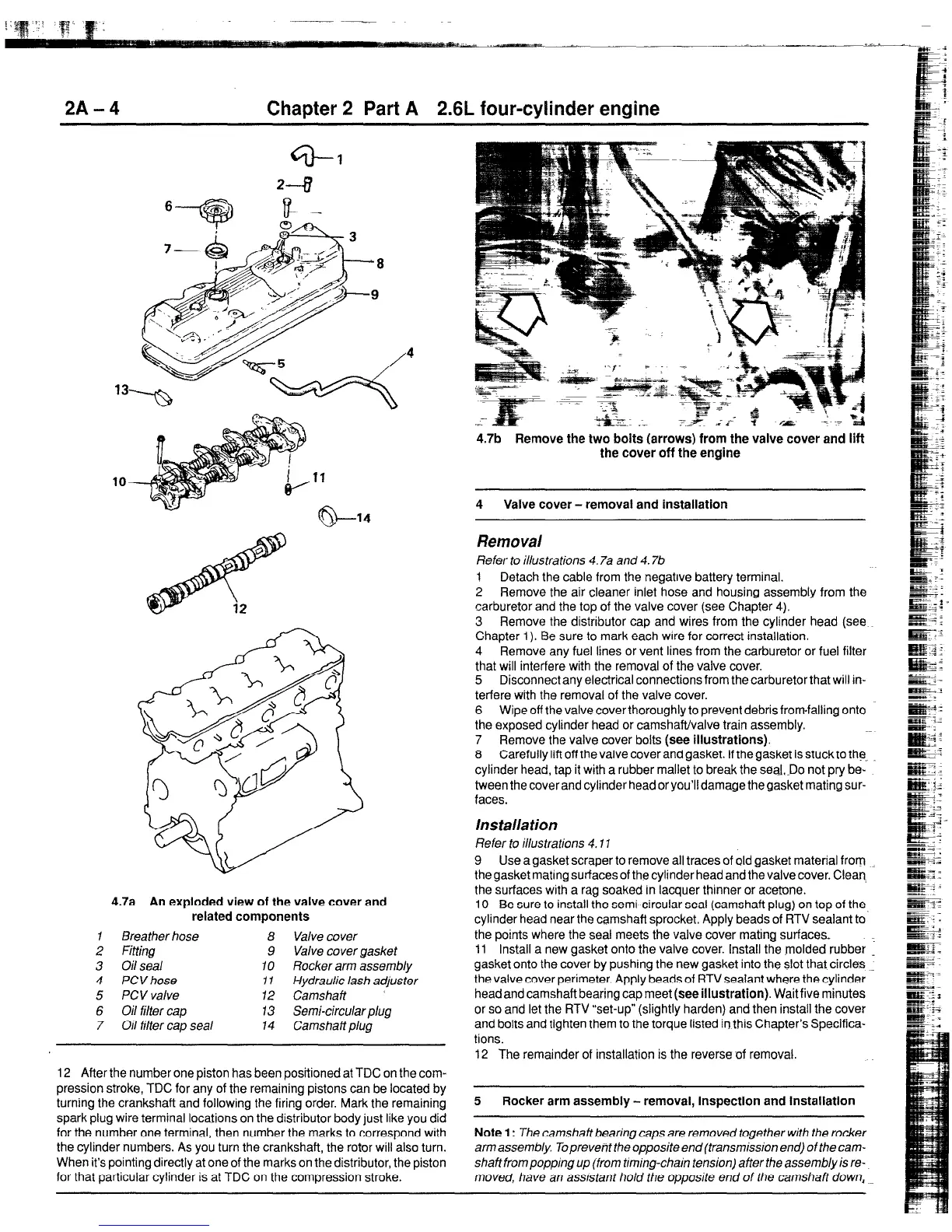
4.7a An exploded view of the valve cover and
related components
I
Breather hose
8 Valve cover
2 Fitting 9 Valve cover gasket
3 Oilseal IO Rocker arm assembly
4 PCVhose 1 I Hydraulic lash adjuster
5 PCV valve 12 Camshaft
6 Oil filter cap 13 Semi-circular plug
7 Oil filter cap seal
14 Camshaftplug
12 After the number one piston has been positioned at TDC on the com-
pression stroke, TDC for any of the remaining pistons can be located by
turning the crankshaft and following the firing order. Mark the remaining
spark plug wire terminal locations on the distributor body just like you did
for the number one terminal, then number the marks to correspond with
the cylinder numbers. As you turn the crankshaft, the rotor will also turn.
When it’s pointing directly at one of the marks on the distributor, the piston
for that particular cylinder is at TDC on the compression stroke.
4.7b Remove the two bolts (arrows) from the valve cover and lift
the cover off the engine
4 Valve cover - removal and installation
Removal
Refer to illustrations 4.7a and 4.7b
1
Detach the cable from the negatrve battery terminal.
2 Remove the air cleaner inlet hose and housing assembly from the
carburetor and the top of the valve cover (see Chapter 4).
3 Remove the distributor cap and wires from the cylinder head (see
Chapter 1). Be sure to mark each wrre for correct installation.
4 Remove any fuel lines or vent lines from the carburetor or fuel filter
that will interfere with the removal of the valve cover.
5 Disconnect any electrical connections from the carburetor that will in-
terfere with the removal of the valve cover.
6 Wipe off the valve cover thoroughly to prevent debris fromfalling onto
the exposed cylinder head or camshaft/valve train assembly.
7 Remove the valve cover bolts (see illustrations).
8 Carefully lift off the valve cover and gasket. If thegasket is stuck to the.
cylinder head, tap it with a rubber mallet to break the seaLDo not pry be-
tween the cover and cylinder head or you’ll damage the gasket mating sur-
faces.
Ins taila tion
Refer to illustrations 4.11
9 Use a gasket scraper to remove all traces of old gasket material from
the gasket mating surfaces of the cylinder head and the valve cover. Clean.
the surfaces with a rag soaked in lacquer thinner or acetone.
10 Be sure to install the semi-circular seal (camshaft plug) on top of the
cylinder head near the camshaft sprocket. Apply beads of RTV sealant to
the points where the seal meets the valve cover mating surfaces
11 Install a new gasket onto the valve cover. Install the molded rubber 1
gasket onto the cover by pushing the new gasket into the slot that circles .
the valve cover perimeter. Apply beads of RTV sealant where the cylinder
head and camshaft bearing cap meet (see illustration). Wait five minutes
or so and let the RTV “set-up” (slightly harden) and then install the cover
and bolts and tighten them to the torque listed in this Chapter’s Specifica-
tions.
12 The remainder of installation is the reversecf removal.
5 Rocker arm assembly - removal, inspection and installation
Note 1: The camshaft bearing caps are removed together with the rocker
arm assembly. Toprevent the opposite end (transmission end) of the cam-
shaft from popping up (from taming-chain tension) after the assembly is re-
moved, have an assrstant ho/d the opposite errd of the camshaft down,
 Loading...


