Chapter 12 Chassis electrical system
17 Power window system -description and check
The power window system operates the electric motors mounted in the
doors which lowerand raise the windows. The system consists of the con-
trol switches, the motors (regulators), glass mechanisms and associated
wiring.
Because of the complexity of the power window system and the spe-
cial tools and techniques required for diagnosis, repair should be left to a
dealer service department or a repair shop. However, it is possible for the
home mechanic to make simple checks of the wiring connections and mo-
tors for minor faults which can be easily repaired. These include:
a) Inspect the power window actuating switches for broken wires and
loose connections.
b) Check the power window fuse/and or circuit breaker.
c) Remove the door panel(s) and check the power window motor
wires to see if they’re loose or damaged. inspect the glass mecha-
nisms for damage which could cause binding.
18 Power door lock system - description and check
The powerdoorlocksystem operates thedoorlockactuators mounted
in each door. The system consists of the switches, actuators and asso-
ciated wiring. Since special tools and techniques are required to diagnose
the system, it should be left to a dealer service department or a repair
shop. However, it is possible for the home mechanic to make simple
checks of the wiring connections and actuators for minor faults which can
be easily repaired. These include:
a) Check the system fuse and/or circuit breaker.
b) Check the switch wires for damage and loose connections.
Check the switches for continuity.
c) Remove the door panel(s) and check the actuator wiring connec-
tions to see if they’re loose or damaged. Inspect the actuator rods
(if equipped) to make sure they aren’t bent or damaged. Inspect the
actuator wiring for damaged or loose connections. The actuator
can be checked by applying battery power momentarily. A discern-
ible click indicates that the solenoid is operating properly.
19 Speedometer cable-replacement
Refer to illustrations 19.2 and 19.4
1 Disconnect the negative cable from the battery.
2 Disconnect the speedometer cable from the transmission (see
illus-
tration).
3 Detach the cable from the routing clips in the engine compartment
and pull it up to provide enough slack to allow disconnection from the
speedometer.
4 Remove the instrument cluster screws, pull the cluster out (see Sec-
tion 14) anddisconnectthespeedometercabtefrom the backofthecluster
(see illustration). Note: On 1991 andlater Montero models with a ratio
adapter, afterremoving theinstrumentcluster, rotate theadapterio theleft
or right to release the locks and pull the adapter out.
5 Remove the cable from the vehicle.
6 * Prior to installation, lubricate the speedometer end of the cable with
spray-on speedometer cable lubricant (available at auto parts stores).
7 Installation is the reverse of removal.
Prior to troubleshooting any circuits, check the fuse and circuit break-
ers (if equipped) to make sure they’re in good condition. Make sure the
battery is properly charged and check the cable connections (see Chap-
ter 1).
20 Wiring diagrams - general information
Sinceitisn’t possible to include all wiring diagrams for every year cov-
ered by this manual, the following diagrams are those that are typical and
most commonly needed.
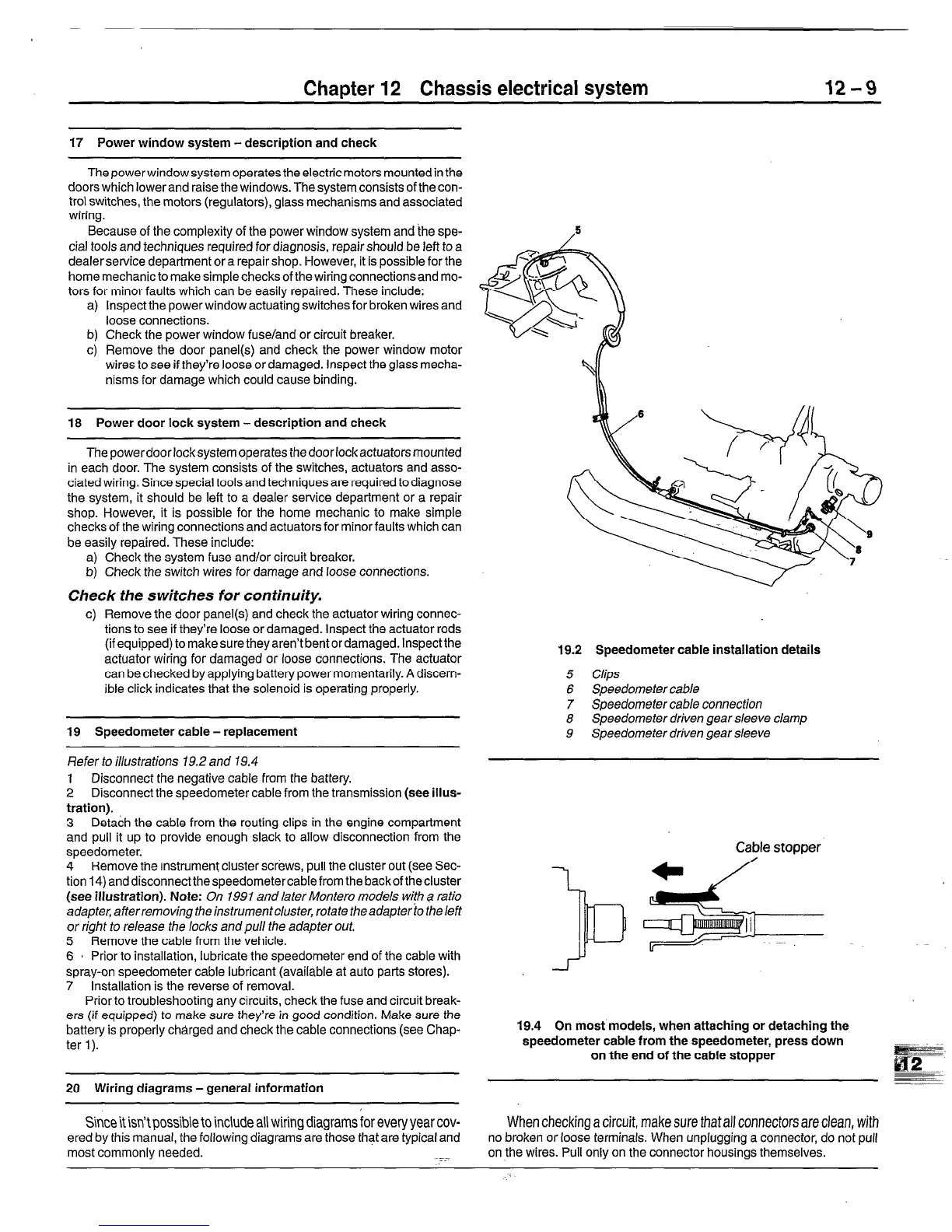
19.2 Speedometer cable installation details
5
Clips
6 Speedometer cable
7 Speedometer cable connection
8 Speedometer driven gear sleeve clamp
9 Speedometer driven gear sleeve
19.4 On most models, when attaching or detaching the
speedometer cable from the speedometer, press down
on the end of the cable stopper
When checking a circuit, make sure that
all connectors are clean, with
no broken or loose terminals. When unplugging a connector, do not pull
on the wires. Pull only on the connector housings themselves.
 Loading...


