Chapter 8 Clutch and driveline 8-5
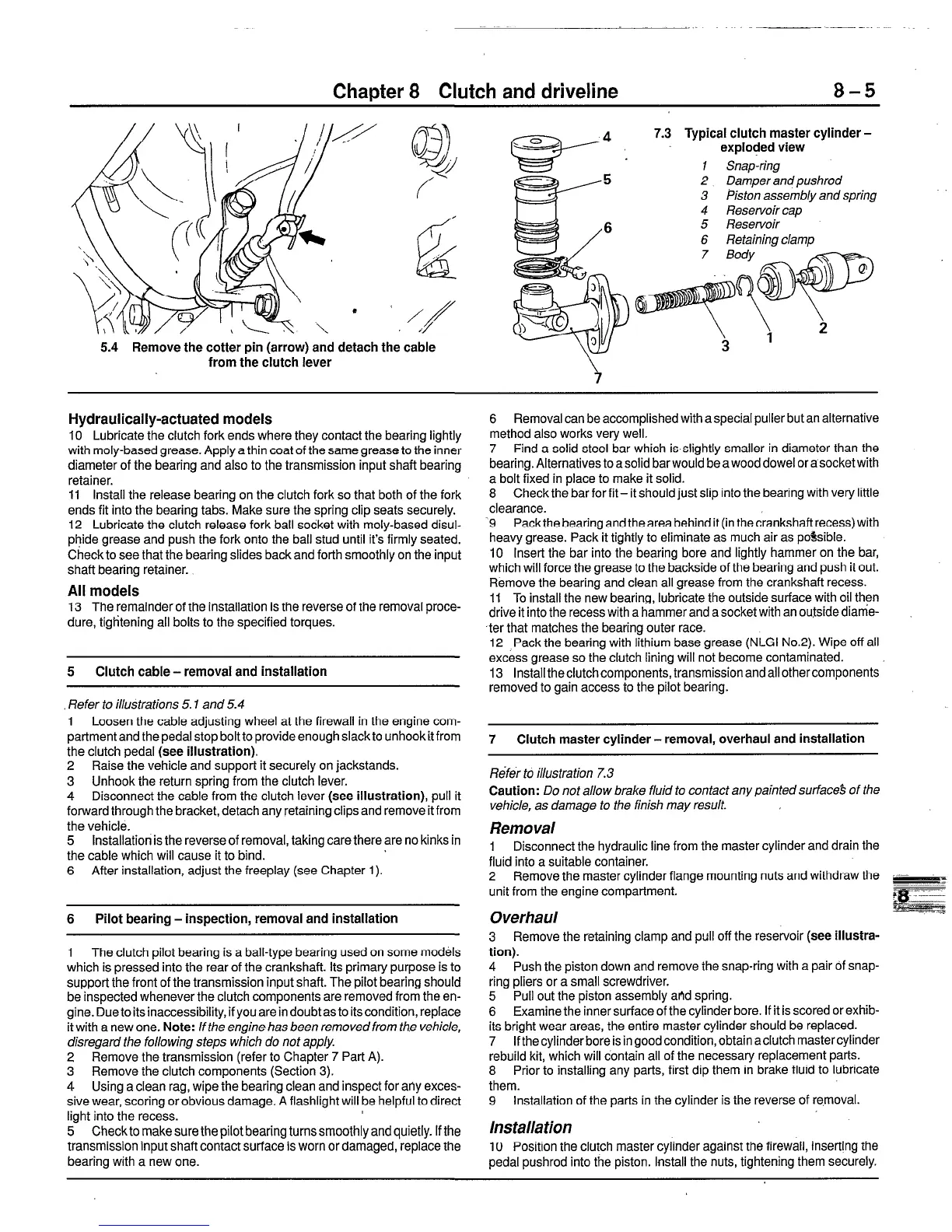
5.4 Remove the cotter pin (arrow) and detach the cable
from the clutch lever
Typical clutch master cylinder -
2 Damper andpushrod
3 Piston assembly and sprjng
4
Reservoir cap
5
Reservoir
6 Retaining clamp
Hydraulically-actuated
models
10 Lubricate the clutch fork ends where they contact the bearing lightly
with moly-based grease. Apply a thin coat of the same grease to the inner
diameter of the bearing and also to the transmission input shaft bearing
retainer.
11 Install the release bearing on the clutch fork so that both of the fork
ends fit into the bearing tabs. Make sure the spring clip seats securely.
12 Lubricate the clutch release fork ball socket with moly-based disul-
phide grease and push the fork onto the ball stud until it’s firmly seated.
Check to see that the bearing slides back and forth smoothly on the input
shaft bearing retainer.
All models
13 The remaindet’of the installation is the reverse of the removal proce-
dure, tigtitening all bolts to the specified torques.
5 Clutch cable-removal and installation
Refer to illustrations 5.1 and 5.4
1 Loosen the cable adjusting wheel at the firewall in the engine com-
partment and the pedal stop bolt to provide enough slack to unhook it from
the clutch pedal (see
illustration).
2 Raise the vehicle and support it securely on jackstands.
3 Unhook the return spring from the clutch lever.
4 Disconnect the cable from the clutch lever
(see illustration),
pull it
forward through the bracket, detach any retaining clips and remove it from
the vehicle.
5 Installation is the reverse of removal, taking care there are no kinks in
the cable which will cause it to bind.
6 After installation, adjust the freeplay (see Chapter 1).
6 Pilot bearing - inspection, removal and installation
1 The clutch pilot bearing is a ball-type bearing used on some models
which is pressed into the rear of the crankshaft. Its primary purpose is to
support the front of the transmission input shaft. The pilot bearing should
be inspected wheneverthe clutch components are removed from the en-
gine. Due to its inaccessibility, if you are in doubt as to its condition, replace
it with a new one.
Note:
If the engine has been removed from the vehicle,
disregard the followjng steps which do not apply.
2 Remove the transmission (refer to Chapter 7 Part A).
3 Remove the clutch components (Section 3).
4 Using a clean rag, wipe the bearing clean and inspect for aily exces-
sive wear, scoring or obvious damage. A flashlight will be helpful to direct
light into the recess.
5 Check to make sure the pilot bearing turns smoothly and quietly. If the
transmission input shaft contact surface is worn or damaged, replace the
bearing with a new one.
6 Removal can be accomplished with a special puller but an alternative
method also works very well.
7 Find a solid steel bar which is slightly smaller in diameter than the
bearing. Alternatives to a solid bar would be a wood dowel or a socket with
a bolt fixed in place to make it solid.
8 Check the bar for fit- it should just slip into the bearing with very little
clearance.
9 Pack the bearing and the area behind it (in the crankshaft recess) with
heavy grease. Pack it tightly to eliminate as much air as pdsible.
10 Insert the bar into the bearing bore and lightly hammer on the bar,
which will force the grease to the backside of the bearing and push it out.
Remove the bearing and clean all grease from the crankshaft recess.
11 To install the new bearing, lubricate the outside surface with oil then
drive it into the recess with a hammer and a socket with an ou$ide dianie-
ter that matches the bearing outer race.
12 Pack the bearing with lithium base grease (NLGI No.2). Wipe off all
excess grease so the clutch lining will not become contaminated.
13 Install the clutch components, transmission and all other components
removed to gain access to the pilot bearing.
7 Clutch master cylinder - removal, overhaul and installation
Rifer to i//us tra tion 7.3
Caution:
Do not allow brake fluid to contact any painted surface’s of the
vehicle, as damage to the finish may result.
Removal
1
Disconnect the hydraulic line from the master cylinder and drain the
fluid into a suitable container.
2 Remove the master cylinder flange mounting nuts and withdraw the
unit from the engine compartment.
Overhaul
3 Remove the retaining clamp and pull off the reservoir
(see illustra-
tion).
4 Push the piston down and remove the snap-ring with a pair of snap-
ring pliers or a small screwdriver.
5 Pull out the piston assembly alld spring.
6 Examine the inner surface of the cylinder bore. If it is scored or exhib-
its bright wear areas, the entire master cylinder should be replaced.
7 If the cylinder bore is in good condition, obtain aclutch master cylinder
rebuild kit, which will contain all of the necessary replacement parts.
8 Prior to installing any parts, first dip them in brake fluid to lubricate
them.
9 Installation of the parts in the cylinder is the reverse of removal.
Installation
IO Position the clutch master cylinder against the firewall, inserting the
pedal pushrod into the piston. Install the nuts, tightening them securely.
 Loading...


