6.- 18 Chader 6
Emissions control systems
11.1
~~ FY
l---J
3 J
H
,T?TEzL czs===-
automatic transmrrsron
Primary throttle valve
Nipple 7’ Vacuum delay
Secondary throttle valve
valve assembly
Vacuum delay valve component layout (some later models
with automatic transmission)
~~~~ 11 Vacuum delay valve (carbureted models only)
Refer fo illustration 11.7
1 Some later vehicles with an automatic transmission are equipped
with avacuum delay
valve (see illustration),
which delays the opening of
the secondary throttle valve and reduces CO and HC emissions during ac-
celeration.
2 Periodically check the vacuum hoses for cracks, leaks and correct in-
stallation. The delay valve itself should be open when avacuum is applied
to one end and restricted when vacuum is applied to the other end.
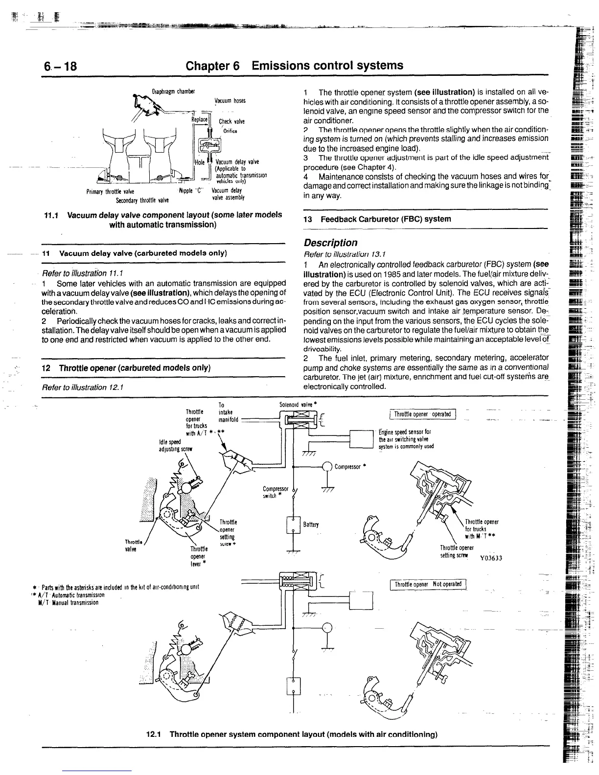
12 Throttle opener (carbureted models only)
Refer to illustration 12.1
1
The throttle opener system (see
illustration)
is installed on all ve-
hicles with arr conditioning. It consists of a throttle opener assembly, a so-
lenoid valve, an engine speed sensor and the compressor switch for the
air conditioner.
2
The throttle openeropens the throttle slightly when the air condition-
ing system is turned on (which prevents stalling and increases emission
due to the increased engine load).
3 The throttle opener adjustment is part of the idle speed adjustment
procedure (see Chapter 4).
4
Maintenance consists of checking the vacuum hoses and wires for,
damage and correct installation and making sure the linkage is not binding-
in any way.
13 Feedback Carburetor (FBC) system
Description
Refer to illustration 13.1
1
An electronically controlled feedback carburetor (FBC) system (see
illustration)
is used on 1985 and later models. The fuel@ir mixture deliv-
ered by the carburetor is controlled by solenoid valves, which are acti-
vated by the ECU (Electronic Control Unit). The ECU receives signajs-
from several sensors, including the exhaust gas oxygen sensor,. throttle
position sensor,vacuum swatch and intake air temperature sensor. De-
pending on the input from the various sensors, the ECU cycles the sole;
noid valves on the carburetor to regulate the fuel/air mixture to obtain the
lowest emissions levels possible while maintaining an acceptable level of.
driveability.
2
The fuel inlet, primary metering, secondary metering, accelerator
pump and choke systems are essentially the same as rn a conventronal
carburetor. The jet (air) mixture, enrichment and fuel cut-off systems are
electronically controlled.
FThrottle opener operated ~---
;1_
Engine speed sensor for
the au switching valve
system is commonly used
opener
lever *
* Par& with le asterisks are included rn the kit of arr-condrbomng unit
:* A/l Automatic trarrsmisrron
M/l Manual transmrrsion
-
1 Throttle opener Not operated (
12.1
Throttle opener system component layout (models with air conditlonlng)
 Loading...


