Chapter 5 Engine electrical systems
11.2 To adjust the air gap between the pick-up and the signal
rotor, loosen the pick-up mounting screws, insert a feeler gauge
of the specified thickness between the pick-up and one of the
signal rotor projections, push the pick-up against the gauge and
tighten the mounting screws
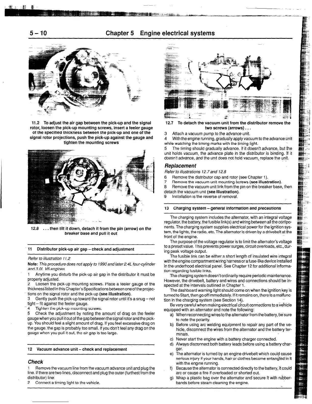
12.8 . . .
then tilt it down, detach it from the pin (arrow) on the
breaker base and pull it out
Ii Distributor pick-up air gap -check and adjustment
Refer to illustration 11.2
Note: This procedure does not apply to 1990 and later 2.41 four-cylinder
and 3.OL V6 engines.
1 Anytime you disturb the pick-up air gap in the distributor it must be
properly adjusted.
2 Loosen the pick-up mounting screws. Place a feeler gauge of the
thicknesslistedin this Chapter’s Specifications between one of the projec-
tions on the signal rotor and the pick-up (see illustration).
3 Gently push the pick-up toward the signal rotor until it’s a snug -not
fight - fit against the feeler gauge.
4 Tighten the pick-up mounting screws.
5 Check the adjustment by noting the amount of drag on the feeler
gauge when you pull it out.of the gap between the signal rotor and the pick-
up. You should feel a slight amount of drag. If you feel excessive drag on
the gaugerthe gap is probably too small. If you don’t feel any drag on the
gauge when you pull it out, the air gap is too large.
12 Vacuum advance unit - check and replacement
Check
1
Remove the vacuum line from the vacuum advance unit and plug the
line. If there are two lines, disconnect and plug the outer (furthest from the
distributor) line.
2 Connect a timing light to the vehicle.
--
.d. : z=Z ~*
- pl,i.
12.7 To detach the vacuum unit from the distributor remove the
two screws (arrows) . . .
3 Attach a vacuum pump to the advance unit.
4 With the engine running, gradually apply vacuum to the advance unit
while watching the timing marks with the timing light.
5 The timing should gradually advance. If it doesn’t advance, but the
unit holds vacuum, the advance plate in the distributor is binding. If it
doesn’t advance, and the unit does not hold vacuum,. replace the unii.
Replacement
Refer to illustrations 72.7 and 12.8
6 Remove the distributor cap and rotor (see Chapter 1).
7 Remove the vacuum unit mounting screws (see illustration).
8 Remove the vacuum unit link from the pin on the breaker base, then
detach the vacuum unit (see illustration).
9 Installation IS the reverse of removal.
13 Charging system - general information and precautions
The charging system includes the alternator, with an integral volfage
regulator, the battery, the fusible link(s) and wiring between all the compo-
nents. The charging system supplies electrical power for the ignition sys-
tem, the lights, the radio, etc. The alternator is driven by a drivebelt at the
front of the engine.
The purpose of the voltage regulator is to limit the alternator’s voltage
to a preset value. This prevents power surges, circuit overloads, etc., dur-
ing peak voltage output.
The fusible link can be either a short length of insulated wire integral
with the engine compartment wiring harness or a fuse-like device installed
in the underhood electrical panel. See Chapter 12 for additional informa-
tion regarding fusible links.
The charging system doesn’t ordinarily require periodic maintenance.
However, the drivebelt, battery and wires and connections should be in-
spected at the intervals outlined in Chapter 1.
The dashboard warning light should come on when the ignition key is
turned to Start, then go off immediately. If it remains on, there is a malfunc-
tion in the charging system (see Section 14).
Be very careful when making electrical circuit connections to a vehicle
equipped with an alternator and note the following:
4
t-4
d
4
e)
When reconnecting wires to the alternator from the battery, be-sure
to note the polarity.
Before using arc welding equipment to repair any part of the ve-
hicle, disconnect the wires from the alternator and the battery ter-
minals
Never start the engine with a battery charger connected.
Always disconnect both battery leads before using a battery char-
ger.
The alternator is turned by an engine drivebelt which could cause
serious injury if your hands, hair or clothes become entangTed in it
with the engine running.
f)
Because the alternator is connected directly to the battery, if could
arc or cause a fire if overloaded or shorted out.
g) Wrap a plastic bag over the alternator and secure it with rubber-
bands before steam cleaning the engine.
 Loading...


