5-12 Chapter 5 Engine electrical systems
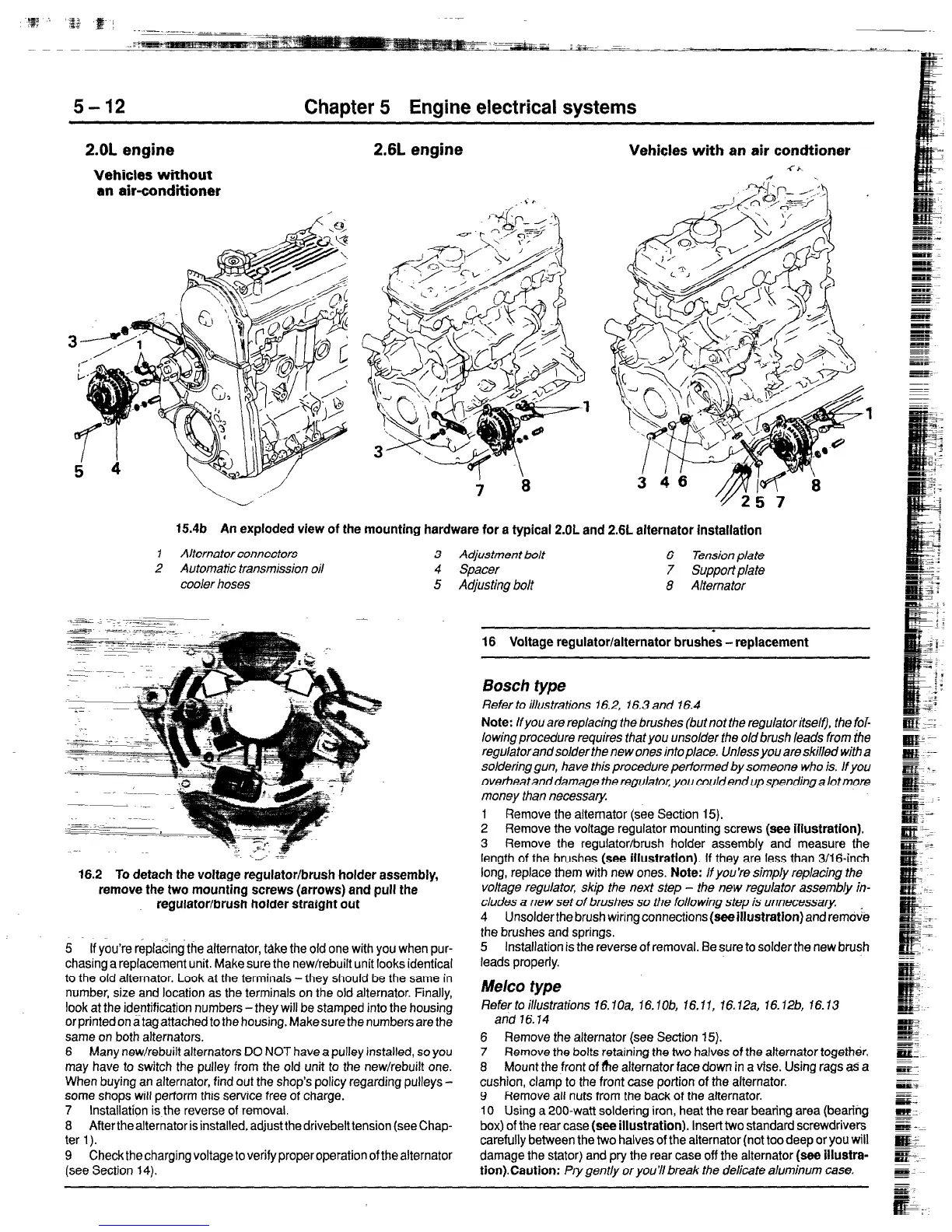
2.OL engine
Vehicles without
an air-conditioner
2.6L engine
Vehicles with an air condtioner
-CA
n
15.4b
An exploded view of the mounting hardware for a typical 2.OL and 2.6L alternator installation
1 Alternator connectors
3 Adjustment ho/t
6 Tension plate
2 Automatic transmission oil 4 Spacer
7
Support plate
cooler hoses 5 Adjusting bolt 8 Alternator
16.2
To detach the voltage regulator/brush holder assembly,
remove the two mounting screws (arrows) and pull the
regulator/brush holder straight out
5 If you’re replacing the alternator, take the old one with you when pur-
chasing a replacement unit. Make sure the new/rebuilt unit looks identical
to the old alternator. Look at the terminals -they should be the same in
number, size and location as the terminals on the old alternator. Finally,
look at the identification numbers -they will be stamped into the housing
or printed on atag
attached
to the housing. Make sure the numbers are the
same on both alternators.
6 Many new/rebuilt alternators DO NOT have a pulley installed, so you
may have to switch the pulley from the old unit to the new/rebuilt one.
When buying an alternator, find out the shop’s policy regarding pulleys -
come shops will perform this service free of charge.
7 Installation is the reverse of removal.
8 ARertheaiternatorisinstalled,adjustthedrivebelttension (seechap-
ter 1).
9 Check the charging voltage to verify proper operation of the alternator
(see Section 14).
1
16 Voltage regulator/alternator brushes - replacement
Bosch type
Refer to illustrations 16.2, 16.3 and 16.4
Note:
If you are replacing the brushes (but not the regulator itself), the fof-
lowing procedure requires that you unsolder the old brush leads from the
regulatorand solder the new ones into place.
Unless you are skrKvd with a
soldering gun, have this procedure performed by someone who is. If you
overheatanddamage theregulator, you couldendupspendinga lotmore
money than necessary
I Remove the alternator (see Section 15).
2 Remove the voltage regulator mounting screws (see illustration).
3
Remove the regulator/brush holder assembly and measure the
length of the brushes (see illustration). If they are less than 3/16-inch
long, replace them with new ones. Note:
lf you’re simpfy rep/acing the
voltage regulator, skip the next step - the new regulator assembly in-
cludes a new set of brushes so the following step is unnecessary
4
Unsolderthe brush wiringconnections(eeeillustration)andremove
the brushes and springs.
5
Installation is the reverse of removal. Be sure to solder the new brush
leads properly.
Melt20 type
Refertoitlustrations 16.1Oa, l&lob, 16.11, 16,12a, 76.12b, 16.13
and
16.14
6
Remove
the alternator (see Section 15).
7 Remove the bolts retaining the two halves of the alternator together.
8
Mount the front of fhe alternator face down in a vise. Using rags as a
cushion, clamp to the front case portion of the alternator.
9
Remove all nuts from the back of the alternator.
10 Using a 200-watt soldering iron, heat the rear bearing area (bearing
box) of the rear case (see illustration). Insert two standard screwdrivers
carefully between the two halves of the alternator (not too deep or you will
damage the stator) and pry the rear case off the alternator (see illustra-
tion).Caution:
Pry gent/y or you’ll break the
delicate
aluminum case.
 Loading...


