ChaWer 4 Fuel and exhaust svstems
Throttle
_ opener
adjusting
screw
SAS-1
SAS-3
14.39 Using a drill bit of the specified diameter,
measure the fast idle opening; if it’s not correct, adjust it
with the fast idle adjusting screw
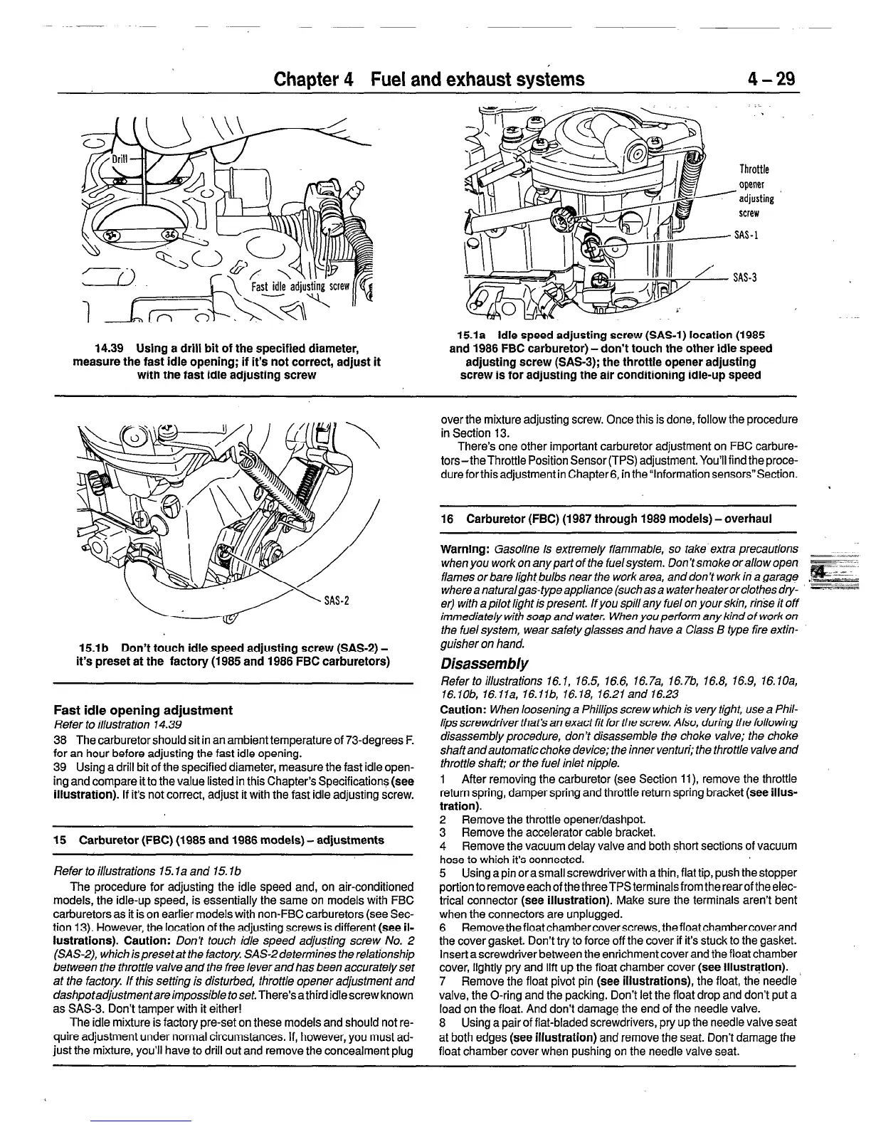
15.la idle speed adjusting screw (SAS-1) location (1985
and 1986 FBC carburetor) - don’t touch the other idle speed
adjusting screw (SAS-3); the throttle opener adjusting
screw is for adjusting the air conditioning idle-up speed
15.lb Don’t touch idle speed adjusting screw (SAS-2) -
it’s preset at the factory (1985 and 1986 FBC carburetors)
Fast idle opening adjustment
Refer to illustration 14.39
38 The carburetor shouldsit in an ambient temperature of 73-degrees F.
for an hour before adjusting the fast idle opening.
39 Using a drill bit of the specified diameter, measure the fast idle open-
ingand compare it to the value listed in this Chapter’s Specification+ (see
illustration). If it’s not correct, adjust it with the fast idle adjusting screw.
15 Carburetor (FBC) (1985 and 1986 models) - adjustments
Refer to illustrations 15. la and 15. lb
The procedure for adjusting the idle speed and, on air-conditioned
models, the idle-up speed, is essentially the same on models with FBC
carburetors as it is on earlier models with non-FBC carburetors (see Sec-
tion 13). However, the location of the adjusting screws is different (see il-
lustrations). Caution:
Don’t touch idle speed adjusting screw No. 2
(SAS-2), which is preset at the factory. SAS-2 determin& the relationship
between the throttle valve and the free lever and has been accurately set
at the factory. If this setting is disturbed, throttle opener adjustment and
dashpotadjustmentareimpossible toset.
There’s athird idle screw known
as SASB. Don’t tamper with it either!
The idle mixture is factory pre-set on these models and should not re-
quire adjustment under normal circumstances. If, however, you must ad-
just the mixture, you’ll have to drill out and remove the concealment plug
over the mixture adjusting screw. Once this is done, follow the procedure
in Section 13.
There’s one other important carburetor adjustment on FBC carbure-
tors - theThrottle Position Sensor (TPS) adjustment. You’ll find the proce-
dure forthis adjustment in Chapter6, in the”lnformation sensors”Section.
16 Carburetor (FBC) (1987 through 1989 models) -overhaul
Warning:
Gasoline is extremely flammable,
so take extra precautions
when you work on any part of the fuel system. Don’t smoke or allow open
flames or bare light bulbs near the work area, and don’t work in a garage
whereanaturalgas-typeappliance (suchasa waterheaterorclothesdty- --==
er) with a pilot light is present. lfyou spill any fuel on your skin, rinse it off
immediately with soap and water. When you perform any kind of work on
the fuel system, wear safety glasses and have a C/ass B type fire extin-
guisher on hand.
Disassembly
Refer to illustrations 16.1, 16.5, 16.6, 16.7a, 16.76, 16.8, 16.9, 16.1Oa,
16.1Ob, 16.11a, 16.11b, 16.18, 16.21and 16.23
Caution:
When loosening a Phillips screw which is very tight, use a Phil-
lips screwdriver that’s an exact fit for the screw. Also, during the following
disassembly procedure, don’t disassemble the choke valve; the choke
shaft and automatic choke device; the inner venturi; the throttle valve and
throttle shaft: or the fuel inlet nipple.
1 After removing the carburetor (see Section ll), remove the throttle
return spring, damper spring and throttle return spring bracket (see illus-
tration).
2 Remove the throttle opener/dashpot.
3 Remove the accelerator cable bracket.
4 Remove the vacuum delay valve and both short sections of vacuum
hose to which it’s connected.
5 Using a pin or a small screwdriver with a thin, fiat tip, push the stopper
portionto removeeachofthethreeTPSterminalsfrom therearoftheelec-
trical connector (see illustration). Make sure the terminals aren’t bent
when the connectors are unplugged.
6 Removethefloatchambercoverscrews,thefloatchambercoverand
the cover gasket. Don’t try to force off the cover if it’s stuck to the gasket.
Insert a screwdriver between the enrichment cover and the float chamber
cover, lightly pry and lift up the float chamber cover (see illusttqtion).
7 Remove the float pivot pin (see illustrations), the float, the needle ’
valve, the O-ring and the packing. Don’t let the float drop and don’t put a
load on the float. And don’t damage the end of the needle valve.
8 Using a pair of flat-bladed screwdrivers, pry up the needle valve seat
at both edges (see illustration) and remove the seat. Don’t damage the
float chamber cover when pushing on the needle valve seat.
 Loading...


