Chapter 4 Fuel and exhaust systems
SCSV terminal
(two pieces)
16.70b SCSV terminal locations
Bimetal
assembly
Terminal
16.11 b Bimetal terminal location
11 Grind off the heads of the two rivets of the bimetal assembly with a
hand grinder, remove the screw (see illustration), remove the plate, the
bimetal assembly and the packing. Knock out the remainder of each rivet
body with a pin punch. Using a pin or asmallscrewdriverwith a thin, flat tip,
push the stopper section and remove the terminal from behind the electri-
cal connector (see illustration). Make sure you don’t bend the terminal
during connector removal. Note: Canadian models don’t have any rivets,
just three screws, ho/ding the bimetal assembly plate.
12 Remove the cover, diaphragm, spring seat, spring, body, spring, dia-
phragm and valve from the carburetor (parts 20 through 27 in illustration
16.7a).
13 Remove the mixture control valve (MCV) assembly and the gasket.
14 Remove the cover, spring, diaphragm, body, spring and diaphragm
(parts 30 through 35 in illustration 16.7a).
15 Remove the bracket (part 36 in illustration 16.7a).
16 Remove the cover, spring, diaphragm and body (parts 37 through 40
in illustration 16.7a).
17 Remove the primary main air jet, the primary pilot jet and the second-
ary pilot jet. When you remove jets, use a screwdriver that’s an exact fit for
their respective slots so you don’t nick or gouge them during removal.
18 Remove the steel ball, weight, ball, plug, O-ring and ball (see illustra-
tion).
19 Remove the screw(s) from the underside of the throttle body. Make
sure the Phillips screwdriver you use is an exact fit to prevent stripping the
crosshead out of the screw. Any burrs created .in the head of this screw
could produce a gap between the throttle body and the manrfold surface.
20 Separate the throttle body from the mixing body. Discard the gasket
between the two. Don’t reuse it.
.
21 Remove the primary main jet and the secondary main jet (see illus-
tration). Again, use an appropriately sized screwdriver that fits tightly to
prevent damage to the jets. The jets are stamped on top to indicate their
size. Be sure to note which size jet goes where so they can be reas-
sembled the same way.
22 Remove the cover, spring and diaphragm (parts 11 through 13 in illus-
tration 16.18).
23 Remove the enrichment jet valve (see illustration). Caution: This
valve has many small parts; don’t lose even one of them! Again, use a
screwdriver whose tip is an exact fit for the cross slots in the head of the jet
toavoiddamaging thejetduringremoval. Usingascrewdriver, takeout the
enrichment jet, the spring and the ball from the enrichment jet valve.
24 Remove the accelerator pump cover assembly, diaphragm, spring,
pump body and gasket (parts 18 through 21 in illustration 16.18).
25 Remove the hose, auxiliary accelerator pump cover, spring, dia-
phragm and check valve (parts 23 through 27).
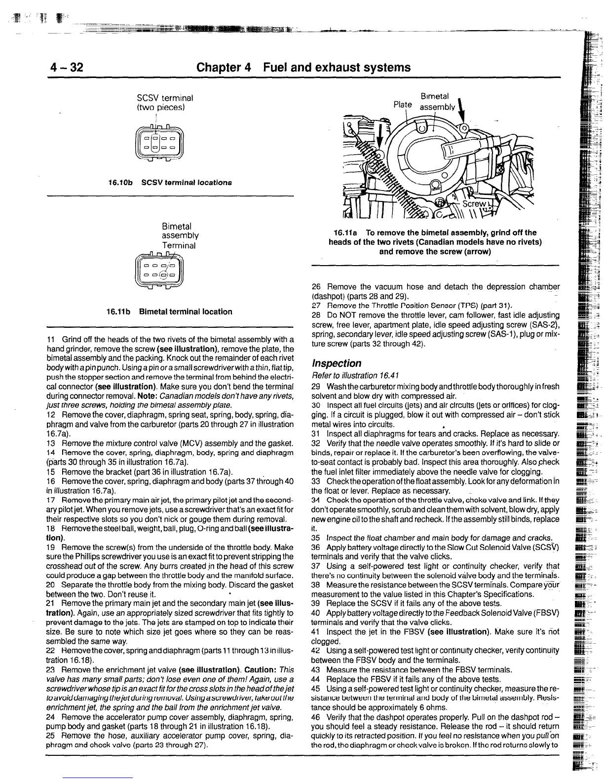
Brmetal
Plate assembly
\
16.11a To remove the bimetal assembly, grind off the
heads of the two rivets (Canadian models have no rivets)
and remove the screw (arrow)
26 Remove the vacuum hose and detach the depression chamber
(dashpot) (parts 28 and 29).
27 Remove the Throttle Position Sensor (TPS) (part 31).
28 Do NOT remove the throttle lever, cam follower, fast idle adjusting
screw, free lever, apartment plate, idle speed adjusting screw (SAS-2),
spring, secondary lever, idle speed adjusting screw (SAS-I), plug or mix-
ture screw (parts 32 through 42).
Inspection
Refer to illustration 16.4 1
29 Wash thecarburetor mixing body andthrottle bodythoroughly in fresh
solvent and blow dry with compressed air.
30 Inspect ail fuel circuits (jets) and air circuits (jets or orifices) for clog-
ging. If a circuit is plugged, blow it out with compressed air - don’t stick
metal wires into circuits.
31 Inspect all diaphragms for tears a’nd cracks. Replace as necessary.
32 Verify that the needle valve operates smoothly. If it’s hard to slide or
binds, repair or replace it. If the carburetor’s been overflowing, the valve-
to-seat contact is probably bad. Inspect this area thoroughly. Alsocheck
the fuel inlet filter immediately above the needle valve for clogging.
33 Check the operation of the float assembly. Look for any deformation in
the float or lever. Replace as necessary.
34 Check the operation of the throttle valve, choke valve and link. If they
don‘t operate smoothly, scrub and clean them with solvent, blow dry, apply
new engine oil to the shaft and recheck. If the assembly still binds, repiace
it.
35 Inspect the float chamber and main body for damage and cracks,
36 Apply battery voltage directly to the Slow Cut Solenoid Valve (SCSV)
terminals and verify that the valve clicks.
37 Using a self-powered test light or continuity checker, verify that
there’s no continuity between the solenoid viilve body and the terminals
38 Measure the resistance between the SCSV terminals. Compare y&Jr
measurement to the value listed in this Chapter’s Specifications.
39 Replace the SCSV if it fails any of the above tests.
40 Apply battery voltage directly to the Feedback Solenoid Valve (FBSV)
terminals and verify that the valve clicks.
41 Inspect the jet in the FBSV (see illustration). Make sure it’s not
clogged.
42 Using a self-powered test light or continuity checker, verify continuity
between the FBSV body and the terminals.
43 Measure the resistance between the FBSV terminals.
44 Replace the FBSV if it fails any of the above tests.
45 Using a self-powered test light or continuity checker, measure the re-
sistance between the terminal and body of the bimetal assembly. Resis-
tance should be approximately 6 ohms.
46 Verify that the dashpot operates properly. Pull on the dashpot rod -
you should feel a steady resistance. Release the rod - it should return
quickly to its retracted position. If you feel no resistance when you pull on
the rod, thediaphragmorcheckvalveis broken. Iftherodreturnsslowlyto
 Loading...


