4-34
Chapter 4 Fuel and exhaust systems
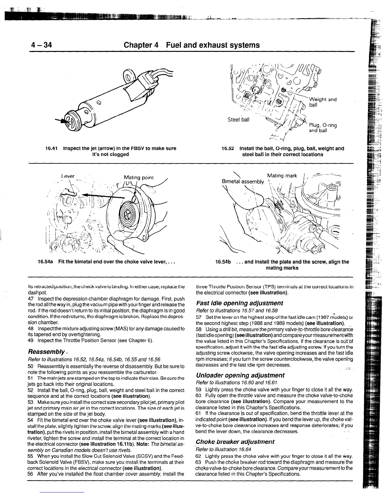
16.41 Inspect the jet (arrow) in the FBSV to make sure 16.52 Install the ball, O-ring, plug, ball, weight and
it’s not clogged
steel ball in their correct locatlons
16.54a Fit the bimetal end over the choke valve lever, . . . 16.54b . . . and install the plate and the screw, align the
mating marks
its retracted position, the check valve is binding. In either case, replace the
dashpot.
47 Inspect the depression chamber diaphragm for damage. First, push
the rod all the way in, plug the vacuum pipe with your finger and release the
rod. If the rod doesn’t return to its initial position, the diaphragm is in good
condition. If the rod returns, the diaphragm is broken. Replace the depres-
sion chamber.
48 Inspect the mixture adjusting screw (MAS) for any damage caused to
its tapered end by overtightening.
49 Inspect the Throttle Position Sensor (see Chapter 6).
Reassembly
I
Refer to illustrations 16.52, 16.54a, 16.54b, 16.55 and 16.56
50 Reassembly is essentially the reverse of disassembly. But be sure to
note the following points as you reassemble the carburetor.
51 The main jets are stamped on the top to indicate their size. Be sure the
jets go back @to their original locations.
52 Install the ball, O-ring, plug, ball, weight and steel ball in the correct
sequence and at the correct locations (see illustration).
53 Make sure you install the correct size secondary pilot jet, primary pilot
jet and primary main air jet in the correct locations. The size of each jet is
stamped on the side of the jet body.
54 Fit the bimetal end over the choke valve lever (see illustration), in-
stall the plate, slightly tighten thescrew, align the mating marks (see illus-
tration), put the rivets in position, install the bimetal assembly with a hand
riveter, tighten the screw and install the terminal at the correct location in
the electrical connector (see illustration 16.11 b). Note: The bimetalas-
sembly on Canadian models doesn’t use rivets.
55 When you install the Slow Cut Solenoid Valve (SCSV) and the Feed-
back Solenoid Valve (FBSV), make sure you install the terminals at their
correct locations in the electrical connector (see illustration).
56 After you’ve installed the float chamber cover assembly, install the
three Throttle Positton Sensor (TPS) terminals at the correct locations in
the electrical connector (see illustration).
Fast idle opening adjustment
Refer to illustrations 76.57and 16.58
57 Set the lever on the highest step of the fast idle cam (1987 m‘odels) or
the second highest step (1988 and i989 models) (see-illustration).
58 Using a drill bit, measure the primary valve-to-throttle bore clearance
(fastidleopening) (seeillustratlon)andcompareyourriTeasur~tientWEh
the value listed in this Chapter’s Specifications. If the clearance is outDf
specification, adjust it with the the fast idle adjusting screw. If you turn the
adjusting screw clockwise, the valve opening increases and the fast idle
rpm increases; if you turn the screw counterclockwise, the valve opening
decreases and the fast idle rpm decreases.
Unloader opening adjustment
Refer fo illustrations 76.60 and 16.61
59 Lightly press the choke valve with your finger to close it all the way.
60 Fully open the throttle valve and measure the choke valve-to-choke
bore clearance (see illustration). Compare your measurement to the
clearance listed in this Chapter’s Specifications.
61 If the clearance is out of specification, bend the throttle lever at the
indicated point (see illustration). If you bend the lever up, the choke val-
ve-to-choke bore clearance increases and response deteriorates; if you
bend the lever down, the clearance decreases.
Choke breaker adjustment
‘Refer to illustration 16.64
62 Lightly press the choke valve with your finger to close it all the way.
63 Push the choke breaker rod toward the diaphragm and measurethe
choke valve-to-choke bore clearance. Compare yourmeasurement to the
clearance listed in this Chapter’s Specifications.
 Loading...


