Chapter 4 Fuel and exhaust systems
24.2 If the injector is malfunctioning, check the resistance
across the terminals and compare your measurement to the
resistance listed in this Chapter’s Specifications - if the indicated
resistance is outside specification, replace the injector
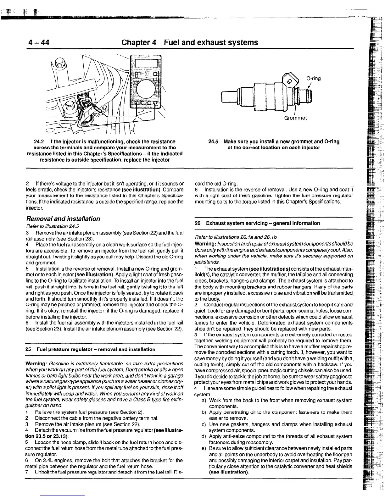
24.5 Make sure you install a new grommet and O-ring
at the correct location on each injector
2 If there’s voltage to the injector but it isn’t operating, or if it sounds or
feels erratic, check the injector’s resistance
(see illustration).
Compare
your measurement to the resistance listed in this Chapter’s Specifica-
tions. If the indicated resistance is outside the specified range, replace the
injector.
Removal and installation
Refer to illustration 24.5
3 Remove the air intake plenum assembly (see Section22)
and
the fuel
rail assembly (see Section 23).
4 Place the fuel rail assembly on a clean work surface so the fuel injec-
tors are accessible. To remove an injector from the fuel rail, gently pull it
straight out. Twisting it slightly as you pull may help. Discard the old O-ring
and grommet.
5 Installation is the reverse of removal. Install a new O-ring and grom-
met onto each injector
(see illustration).
Apply a light coat of fresh gaso-
line to the O-ring to facilitate installation. To install an injector into the fuel
rail, push it straight into its bore in the fuel rail, gently twisting it to the left
and right as you push. Once the injector is fully seated, try to rotate it back
and forth. It should turn smoothly if its properly installed. If it doesn’t, the
O-ring may be pinched or jammed; remove the injector and check the O-
ring. If it’s okay, reinstall the injector; if the O-ring is damaged, replace it
before installing the injector.
6 Install the fuel rail assembly with the injectors installed in the fuel rail
(see Section 23). Install the air intake plenum assembly (see Section 22).
25 Fuel pressure regulator - removal and installation
Warning:
Gasoline is extremely flammable, so take extra precautions
when you work an any part of the fuel system. Don’t smoke or allow open
flames or bare light bulbs near the work area, and don’t work in a garage
wherea naturalgas-type appliance (such as a waterheaterorctothesdry-
er) with a pilot tight is present. If you spill any fuel on your skin, rinse it off
immediately with soap and water. When you perform any kind of work on
the fuel system, wear safety glasses and have a Class B type fire extin-
guisher on hand.
1 Relieve the system fuel pressure (see Section 2).
2 Disconnectthe cable from the negative battery terminal.
3 Remove the air intake plenum (see Section 22).
4 Detach the vacuum line from the fuel pressure regulator
(see illustra-
tion 23.5 or 23.13).
5 Loosen the hose clamp, slide it back on the fuel return hose and dis-
connect the fuel return hose from the metal tube attached to the fuel pres-
sure regulator.
6 On 2.4L engines, remove the bolt that attaches the bracket for the
metal pipe between the regulator and the fuel return hose.
7 Unbolt the fuel pressure regulator and detach it from the fuel rail. Dis-
card the old O-ring.
8 Installation is the reverse of removal. Use a new O-ring and coat it
with a light coat of fresh gasoline. Tighten the fuel pressure regulator
mounting bolts to the torque listed in this Chapter’s Specifications.
26 Exhaust system servicing -general information
Refer to illustrations 26. la and 26. lb
Warnlng:
lnspectionandrepairofexhaustsystemcomponentsshoul~be
done only with the engine and exhaust components completely cool. Also,
when working under the vehicle, make sure it’s securely supported on
jackstands.
1 The exhaust system
(see illustrations)
consists of the exhaust man-
ifold(s), the catalytic converter, the muffler, the tailpipe and all connecting
pipes, brackets, hangers and clamps. The exhaust system is attached tc
the body with mounting brackets and rubber hangers. If any of the parts
are improperly installed, excessive noise and vibration wiU be transmitted~
to the body.
2 Conduct regular inspections of theexttaustsystem to keep it safe and
quiet. Look for any damaged or bent parts, open seams, holes, loose con-
nections, excessive corrosion or other defects which could allow exhaust
fumes to enter the vehicle. Deteriorated exhaust system components
shouldn’t be repaired; they should be replaced with new parts.
3 If the exhaust system components are extremely corroded or rusted
together, welding equipment will probably be required to remove them.
The convenient way to accomplish this is to have a muffler repair shop re-
move the corroded sections with a cutting torch. If, however, you want to
save money by doing it yourself (and you don’t have a welding outfit with a.
cutting torch), simply cut off the old components with a hacksaw. If you
have compressed air, special pneumatic cutting chisels can also be used.
If you do decide to tackle the job at home, be sure to wear safety goggles to
protect your eyes from metal chips and work gloves to protect your hands.
4 Here are some simple guidelines to follow when repairing the exhaust
system:
a) Work from the back to the front when removing exhaust system
components.
b) Apply penetrating oil to the component fasteners to make them.
easier to remove.
c) Use new gaskets, hangers and clamps when installing exhaust
system components.
d) Apply anti-seize compound to the threads of all exhaust system
fasteners during reassembly.
e) Be sure to allow suff icrent clearance between newly installed parts
and all points on the underbody to avoid overheating the floor pan
and possibly damaging the interior carpet and insulation. Pay par-
ticularly close attention to the catalytic converter and heat shields
(see illustration).
 Loading...


