2A-12
Chapter 2 Part A 2.6L four-cylinder engine
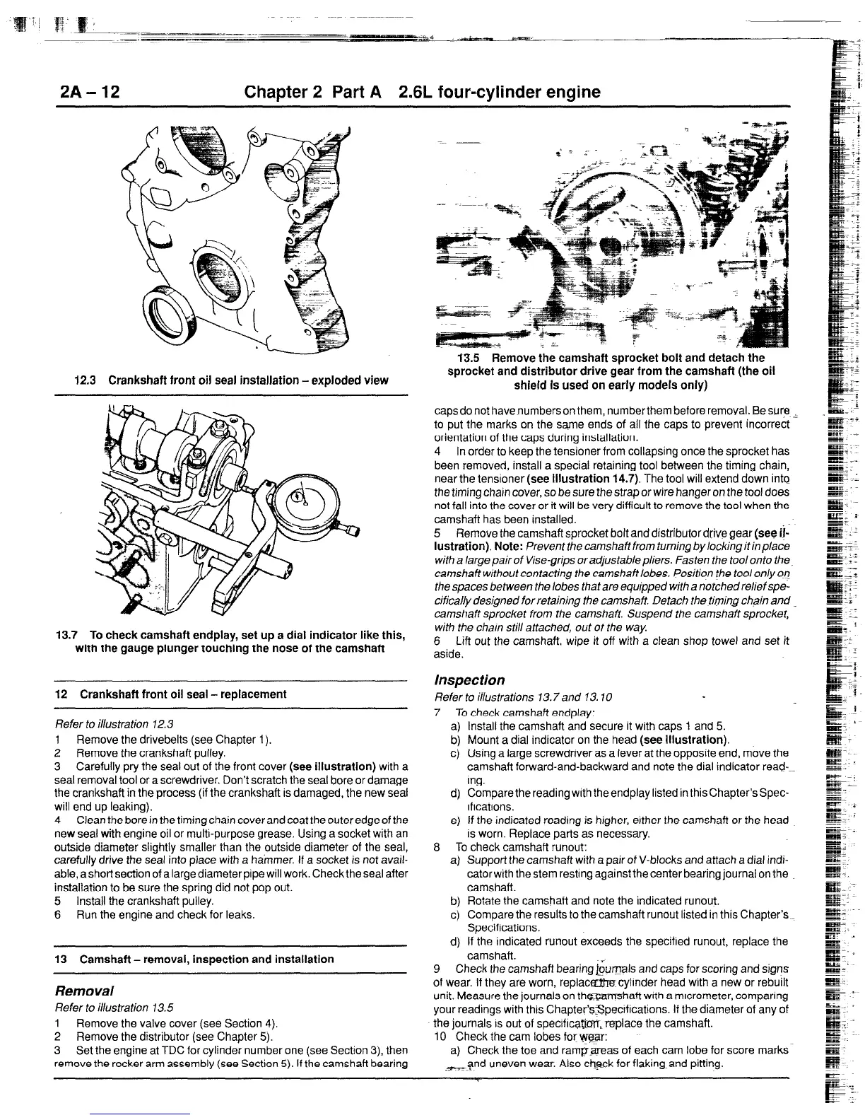
12.3 Crankshaft front oil seal installation -exploded view
13.7 To check camshaft endplay, set up a dial indicator like this,
with the gauge plunger touching the nose of the camshaft
12 Crankshaft front oil seal - replacement
Refer to illustration 72.3
1 Remove the drivebelts (see Chapter 1).
2 Remove the crankshaft pulley.
3 Carefully pry the seal out of the front cover
(see illustration)
with a
seal removal tool or a screwdriver. Don’t scratch the seal bore or damage
the crankshaft in the process (if the crankshaft is damaged, the new seal
will end up leaking).
4 Clean the bore in the timing chain cover and coat the outer edge of the
new seal with engine oil or multi-purpose grease. Using a socket with an
outside diameter slightly smaller than the outside diameter of the seal,
carefully drive the seal into place with a hammer. If a socket is not avail-
able, ashortsection of a large diameter pipewill work. Check the seal after
installation to be sure the spring did not pop out.
5 Install the crankshaft pulley.
6 Run the engine and check for leaks.
13 Camshaft - removal, inspection and installation
Removal
Refer to illustration 13.5
1
Remove the valve cover (see Section 4).
2 Remove the distributor (see Chapter 5).
3 Set the engine at TDC for cylinder number one (see Section 3), then
remove the rocker arm assembly (see Section 5). If the camshaft bearing
13.5 Remove the camshaft sprocket bolt and detach the
sprocket and distributor drive gear from the camshaft (the oil
shield is used on early models only)
capsdo not have numberson them, numberthem before removal. Be sure
to put the marks on the same ends of all the caps to prevent incorrect
orientation of the caps during installation.
4 In order to keep the tensioner from collapsing once the sprocket has
been removed, install a special retaining tool between the timing chain,
near the tensloner
(see Illustration 14.7).
The tool will extend down into
the timing chain cover, so be sure the strap or wire hanger on the tool does
not fall into the cover or it will be very difficult to remove the tool when the
camshaft has been installed.
5 Remove the camshaft sprocket bolt anddistributordrive gear (see
ii-
lustration). Note:
Prevent the camshaft from turning by locking it inplace
with a largepairof Vise-grips oradjustablepliers. Fasten the too/onto the,
camshaft without contacting the camshaft lobes. Position the tool only OQ
the spaces between the lobes that are equipped with a noYched relief spe-
cifically designed for retaining the camshaft. Detach the timing chain and
camshaft sprocket from the camshaft. Suspend the camshaft sprocket,
with the cha/n still attached, out ot the way.
8 Lift out the camshaft, wipe it off with a clean shop towel and set it
aside.
Inspection
Refer to illustrations 13.7 and 13.10
7 To check camshaft endplay:
a) Install the camshaft and secure it with caps 1 and 5.
b) Mount a dial indicator on the head
(see illustration).
c) Using a large screwdriver as a lever at the opposite end, move the
camshaft forward-and-backward and note the dial indicator read---
mg.
d) Comparethe reading with theendplay listed in this Chapter’s Spec-
Iftcatlons.
e) If the indicated reading is higher, either the camshaft or the head
is worn. Replace parts as necessary.
8 To check camshaft runout:
a) Support the camshaft with a pair of V-blocks and attach a dial indi-
cator with the stem resting against the center bearing journal on the
camshaft.
b) Rotate the camshaft and note the indicated runout.
cj Compare the results to the camshaft runout listed in this Chapter’s
Specifications.
d) If the indicated runout exceeds the specified runout, replace the
camshaft.
9 Check the camshaft bearing j&Eals and caps for scoring and signs
of wear. If they are worn, replac&&cylmder head with a new or rebuilt
unit. Measure the journals on thmhaft with a micrometer, comparing
your readings with this Chapter’sSpectfications. If the diameter of any of
the journals IS out of spectflca@frr,replace the camshaft.
10 Check the cam lobes for \:
a) Check the toe and ram-areas of each cam lobe for score marks
,?nd uneven wear. Also check for flaking and pitting.
 Loading...


