2C-4 Chapter 2 Part C
3.OL V6 engine
12,
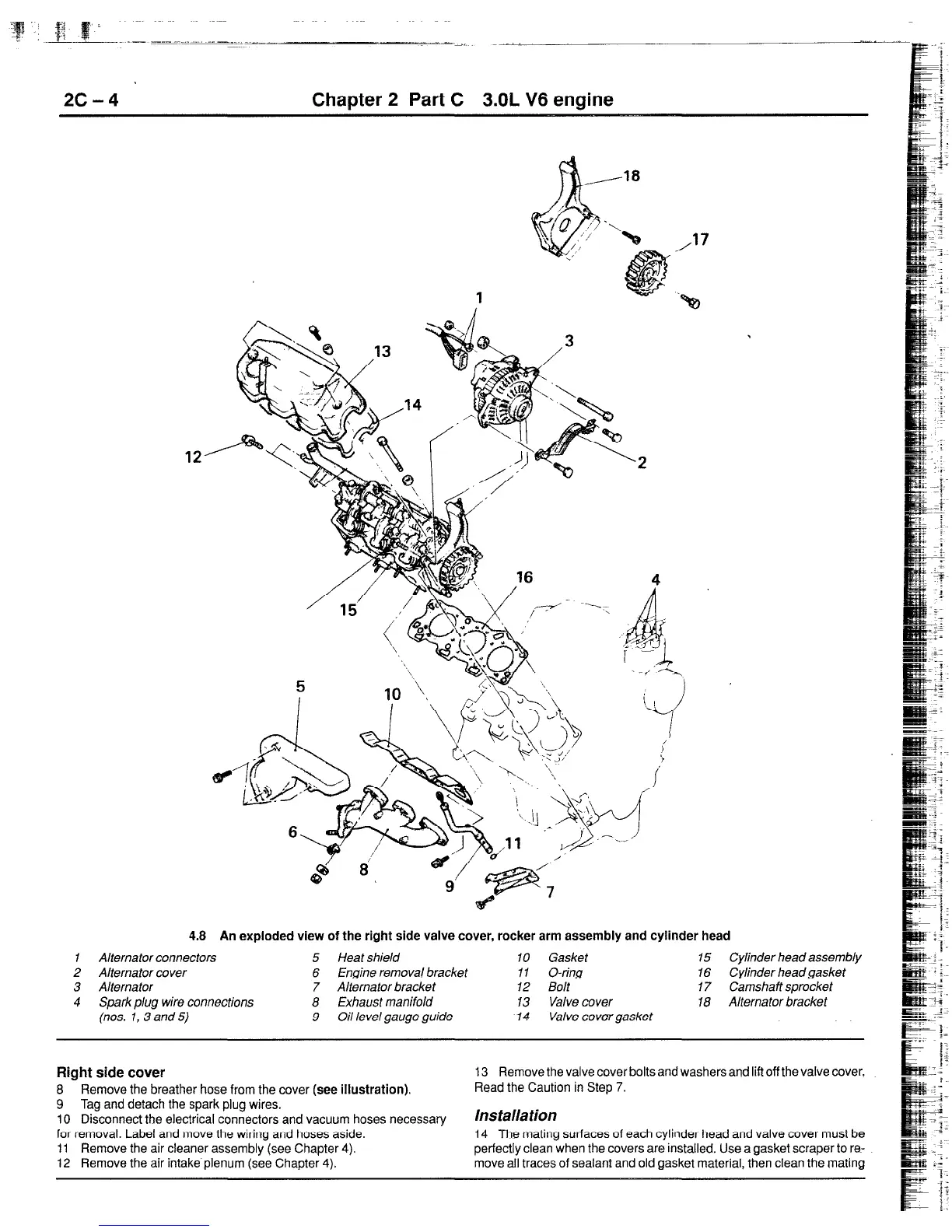
4.8 An exploded view of the right side valve cover, rocker arm assembly and cylinder head
I Alternator connectors
5 Heat shield 10 Gasket 15 Cylinder head assembly
2 Alternator cover 6 Engine removal bracket 11 O-ring
16 Cylinder headgasket
3 Alternator
7 Alternator bracket 12 Bolt 17 Camshaft sprocket
4 Spark plug wire connections 8 Exhaust manifold
13 Valve cover f 8 Alternator bracket
(nos. 1, 3 and 5)
9 Oil level gauge guide 14 Valve covergasket
Right side cover
8 Remove the breather hose from the cover
(see illustration).
9 Tag and detach the spark plug wires.
10 Disconnect the electrical connectors and vacuum hoses necessary
for removal. Label and move the wiring and hoses aside.
11 Remove the air cleaner assembly (see Chapter 4).
12 Remove the air intake plenum (see Chapter 4).
13 Remove the valve cover bolts and washers and lift off the valve cover.
Read the Caution in Step 7.
lf?SfiJk3fiO~
14 The mating surfaces of each cylinder head and valve cover must be
perfectly clean when the covers are installed. Use a gasket scraper to re:
move all traces of sealant and old gasket material, then clean the mating
 Loading...


