Chapter 2 Part C
3.OL V6 engine
2C-7
22
,25
27, A%
b--J
324
(
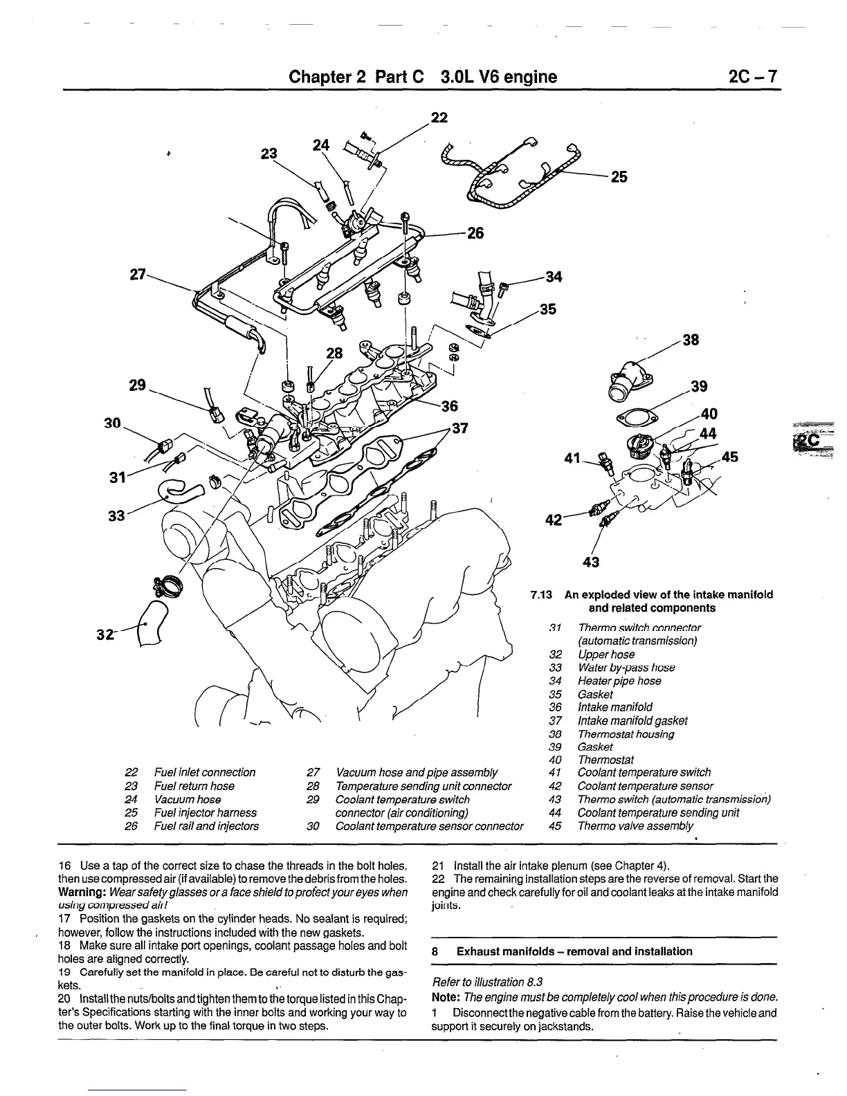
22 Fuel inlet connection 27 Vacuum hose and pipe assembly
23 Fuel return hose 28 Temperature sending unit connector
24 Vacuum hose
29 Coolant temperature switch
25 Fuel injector harness
connector (air conditioning)
42
7.13 An exploded view of the intake manifold
31
32
33
34
35
36
37
38
39
40
41
42
43
44
26 Fuel rail and injectors 30 Coolant temperature sensor connector
45
and related components
Therm0 switch connector
{automatic transmission)
Upper hose
Water by-pass hose
Heater pipe hose
Gasket
intake manifold
intake manifold gasket
Thermostat housing
Gasket
Thermostat
Coolant temperature switch
Coolant temperature sensor
Therm0 switch (automatic transmission)
Coo/ant temperature sending unit
Therm0 valve assembly
16 Use a tap of the correct size to chase the threads in the bolt holes,
then use compressed air (if available) to remove the debris from the holes.
Warning:
Wearsafetyglassesora faceshield toproti3ctyoureyes when
using compressed air!
17 Position the gaskets on the cylinder heads. No sealant is required;
however, follow the instructions included with the new gaskets.
18
Make sure all intake port openings, coolant passage holes and bolt
holes are aligned correctly.
19 Carefully set the manifold in place. Be careful not to disturb the gas-
kets.
20 Install the nuts/bolts and tighten them to the torque listed in this Chap-
ter’s Specifications starting with the inner bolts and working your way to
the outer bolts. Work up to the final torque in two steps.
21 Install the air intake plenum (see Chapter 4).
22 The remaining installation steps are the reverse of removal. Start the
engine and check carefully for oil and coolant leaks at the intake manifold
joints.
8
Exhaust manifolds - removal and installation
Refer to illustration 8.3
Note:
The engine must be completely cool when this procedure is done.
1 Disconnect the negative cable from the battery. Raise the vehicle and
support it securely on jackstands.
 Loading...


