Chapter 2 Part C 3.OL V6 engine 2C-13
TIMING
BELT
END
CYLINDiR HEAD
BOLT $ND WASHER
14.12 Cylinder head bolt removal sequence
TIMING
BELT
END
14.23
Cylinder head bolt tightening sequence
P-
10 mm
ALLEN HEX
CYLINDER HEAD
BOLT A,ND WASHER
must be perfectly clean when the heads are installed.
17 Use a gasket scraper to remove all traces of carbon and old gasket
material, then clean the mating surfaces with lacquerthinner or acetone. If
there’s oil on the mating surfaces when the heads are installed, the gas-
kets may not seal correctly and leaks may develop. Use a vacuum cleaner
to remove any debris that falls into the cylinders.
18 Check the block and head mating surfaces for nicks, deep scratches
and other damage. If damage is slight, it can be removed with a file- if it’s
excessive, machining may be the only alternative.
19 Use a tap of the correct size to chase the threads in the head bolt
holes. Mount each bolt in a vise and run a die down the threads to remove
corrosion and restore the threads. Dirt, corrosion, sealant and damaged
threads will affect torque readings. Ensure that the threaded holes in the
block are clean and dry.
20 Position the new gaskets over the dowel pins on the block.
21 Carefully position the heads on the block without disturbing the gas-
kets.
22 Lightly oil the threads and install the bolts in their original locations.
Tighten them finger tight.
23 Follow the recommended sequence and tighten the bolts in three
steps to the torque listed in this Chapter’s Specifications (see illustra-
tion).
24 The remaining installation steps are the reverse of removal.
25 Add coolant and change the engine oil and filter (see Chapter I), then
start the engine and check carefully for oil and coolant leaks.
15 Camshaft(s) - removal and installation
Removal
1 Position the engine at TDC on the compression stroke for the number
1 cylinder (see Section 3). Remove the timing belt and camshaft sprockets
(seesections 10 and 12). Note:
Ifyou’reonlyremovingonecamshaftand
you want to save time by not removing and installing the timing belt and
re-timing the engine, you can unfasten the camshaft sprocket and sus-
pend it out of the way - with the belt still attached - by a piece of rope. Be
sure the rope keeps firm tension on the be/t so the be/t won’t become dis-
engaged from any of the sprockets.
2 If you’re removing the left (driver’s side) cylinder head, remove the
bolts and gently pry off the distributor drive adapter (see illustration
12.5).
3 Remove the rocker arm assembly (see Section 5).
4 Carefully pry the camshaft plugs from the rear section of the cylinder
head. Don’t scratch or nick the camshaft in the process!
5 Carefully lift the camshaft from the cylinder head. Jnspect the cam-
shaft as described in Section 16.
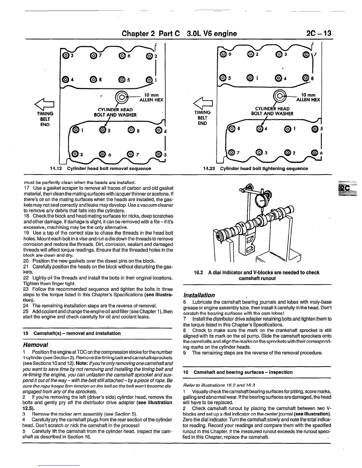
16.2 A dial indicator and V-blocks are needed to check
camshaft runout
Ins talla tion
6 Lubricate the camshaft bearing journals and lobes with moly-base
grease or engine assembly lube, then install it carefully in the head. Don’t
scratch the bearing surfaces with the cam lobes!
7 Install the distributor drive adapter retaining bolts and tighten them to
the torque listed in this Chapter’s Specifications.
8 Check to make sure the mark on the crankshaft sprocket is still
aligned with its mark on the oil pump. Slide the camshaft sprockets onto
the camshafts and align the marks on the sprockets with theircorrespond-
ing marks on the cylinder heads.
9 The remaining steps are the reverse of the removal procedure.
16 Camshaft and bearing surfaces - inspection
Refer to illustrations 16.2 and 16.3
1 Visuallycheckthecamsha’ftbearingsurfacesforpitting,scoremarks,
galling and abnormal wear. If the bearing surfacesaredamaged, the head
will have to be replaced.
2 Check camshaft runout by placing the camshaft between two V-
blocks and set up a dial indicator on the center journal (see illustration).
Zero the dial indicator. Turn the camshaft slowly and note the total indica-
tor reading. Record your readings and compare them with the specified
runout in this Chapter. If the measured runout exceeds the runout speci-
fied in this Chapter, replace the camshaft.
 Loading...


