EasyManua.ls Logo

Mitsubishi PKFY-P32VHM-E User Manual

Mitsubishi PKFY-P32VHM-E
30 pages
To Next Page IconTo Next Page
Page #1 background imageLoading...
Page #1 background image
TECHNICAL & SERVICE MANUAL
CONTENTS
1. TECHNICAL CHANGES .........................2
2. SAFETY PRECAUTION
..........................
3
3. PART NAMES AND FUNCTIONS
..........
5
4. SPECIFICATION
...................................
12
5. OUTLINES AND DIMENSIONS
............
15
6. WIRING DIAGRAM
...............................
16
7. REFRIGERANT SYSTEM DIAGRAM
........
18
8. TROUBLESHOOTING
..........................
18
9. DISASSEMBLY PROCEDURE
.............
26
Indoor unit
[Model names] [Service Ref.]
No. OCH442
REVISED EDITION-B
INDOOR UNIT
SPLIT-TYPE, HEAT PUMP AIR CONDITIONERS
R410A
Note:
This manual describes
only service data of the
indoor units.
RoHS compliant products
have <G> mark on the
spec name plate.
December 2012
PARTS CATALOG (OCB442)
Revision:
PKFY-P32/40/50VHM-ER2
have been added in
REVISED EDITION-B.
Some descriptions have
been modified.
Plase void OCH442
REVISED EDITION-A.
PKFY-P32VHM-E
PKFY-P32VHM-ER1
PKFY-P32VHM-ER2
PKFY-P40VHM-E
PKFY-P40VHM-ER1
PKFY-P40VHM-ER2
PKFY-P50VHM-E
PKFY-P50VHM-ER1
PKFY-P50VHM-ER2
PKFY-P32VHM-E
PKFY-P40VHM-E
PKFY-P50VHM-E
Question and Answer IconNeed help?

Do you have a question about the Mitsubishi PKFY-P32VHM-E and is the answer not in the manual?

Mitsubishi PKFY-P32VHM-E Specifications

General IconGeneral
BrandMitsubishi
ModelPKFY-P32VHM-E
CategoryAir Conditioner
LanguageEnglish

Summary

Safety Precautions

Refrigerant Handling Cautions

Guidelines for safe handling and use of refrigerants, tools, and procedures.

Service and Tool Cautions

Specific cautions for servicing the unit and using specialized R410A refrigerant tools.

Specifications

Unit Specifications

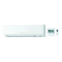
Presents detailed technical specifications for the indoor units, including capacity and power.

Unit Specifications (ER1/ER2 Models)

Details technical specifications for the ER1 and ER2 model variations of the indoor units.

Wiring Diagram

Troubleshooting

Part Resistance Checks

Guides on how to check the resistance of key components like thermistors and motors.

Valve Operation and Troubleshooting

Covers output pulse signals, valve operation, and common troubleshooting issues for the expansion valve.

DC Fan Motor Checks

Provides a step-by-step procedure for diagnosing and troubleshooting the indoor fan motor.

Disassembly Procedure

Removing Lower Unit and Front Panel

Step-by-step instructions for removing the lower side and front panel of the indoor unit.

Removing Controller Boards and Electrical Box

Procedures for removing the indoor controller board, wireless controller board, and electrical box.

Related product manuals