OC275-1
CONTENTS
1. TECHNICAL CHANGE ··················································································OC275- 2
2. FEATURES·····································································································OC275- 3
3. PART NAME AND FUNCTIONS····································································OC275- 4
4. SPECIFICATIONS··························································································OC275- 5
5. DATA ··············································································································OC275- 6
6. OUTLINES AND DIMENSIONS·····································································OC275-13
7. REFRIGERANT SYSTEM DIAGRAM····························································OC275-15
8. WIRING DIAGRAM ························································································OC275-16
9. OPERATION FLOW-CHART ·········································································OC275-17
10. MICROPROCESSOR CONTROL··································································OC275-20
11. TROUBLESHOOTING····················································································OC275-32
12. DISASSEMBLY PROCEDURE ······································································OC275-35
13. PARTS LIST ···································································································OC275-38
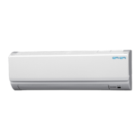
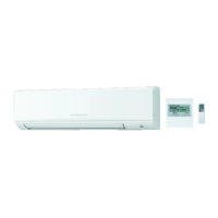
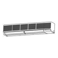
PK18FL3
PK24FL3
PK30FL3
PK36FL3
OC275--1.qxp 01/12/14 3:06 PM Page 1


 Loading...