38
PLH-P1.6KAH.UK / PUH-P1.6VGA, PUH-P1.6YGA
PLH-P2KAH.UK / PUH-P2VGA, PUH-P2YGA
PLH-P2.5KAH.UK / PUH-P2.5VGA1, PUH-P2.5YGA1
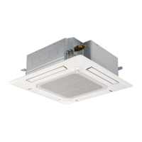
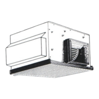
Indoor unit
Refrigerant pipe
15.88
mm( 5/8")
(with heat insulator)
Flexible tube
Ball valve
Strainer
4-way valve
Muffler
Service
port
Service
port
High pressure
switch
Outdoor unit
Strainer Strainer
Compressor
Accumulator
Drier
Ball valve
(with service port)
Refrigerant pipe
9.52
mm( 3/8")
(with heat insulator)
Distributor
with
strainer
Distributor
with
strainer
Thermistor
(TH1)
Thermistor
(TH5)
Thermistor
(TH4)
Thermistor
(TH6)
Thermistor
(TH3)
Thermistor
(TH2)
Strainer
Flared
connection
<4-way valve solenoid coil>
Heating ON
Cooling OFF
Refrigerant flow in cooling
Refrigerant flow in heating
Linear
expansion
valve
Unit : mm
Indoor unit
Refrigerant pipe
15.88
mm( 5/8")
(with heat insulator)
Flexible tube
Ball valve
Strainer
4-way valve
Muffler
Service
port
Service
port
High pressure
switch
Outdoor unit
Strainer Strainer
Compressor
Accumulator
Drier
Stop valve
(with service port)
Refrigerant pipe
9.52
mm( 3/8")
(with heat insulator)
Distributor
with
strainer
Distributor
with
strainer
Thermistor
(TH1)
Thermistor
(TH5)
Thermistor
(TH4)
Thermistor
(TH6)
Thermistor
(TH3)
Thermistor
(TH2)
Strainer
Flared
connection
<4-way valve solenoid coil>
Heating ON
Cooling OFF
Refrigerant flow in cooling
Refrigerant flow in heating
Linear
expansion
valve
Strainer
PLH-P1.6KAH.UK, PLH-P1.6KAH1.UK / PUH-P1.6VGAA.UK, PUH-P1.6YGAA.UK
PLH-P2KAH.UK, PLH-P2KAH1.UK / PUH-P2VGAA.UK, PUH-P2YGAA.UK
PLH-P2.5KAH.UK, PLH-P2.5KAH1.UK / PUH-P2.5VGAA.UK, PUH-P2.5YGAA.UK
9
REFRIGERANT SYSTEM DIAGRAM
OC235B---2.qxp 04.9.29 3:23 PM Page 38

 Loading...
