26
OPERATING PROCEDURE PHOTOS
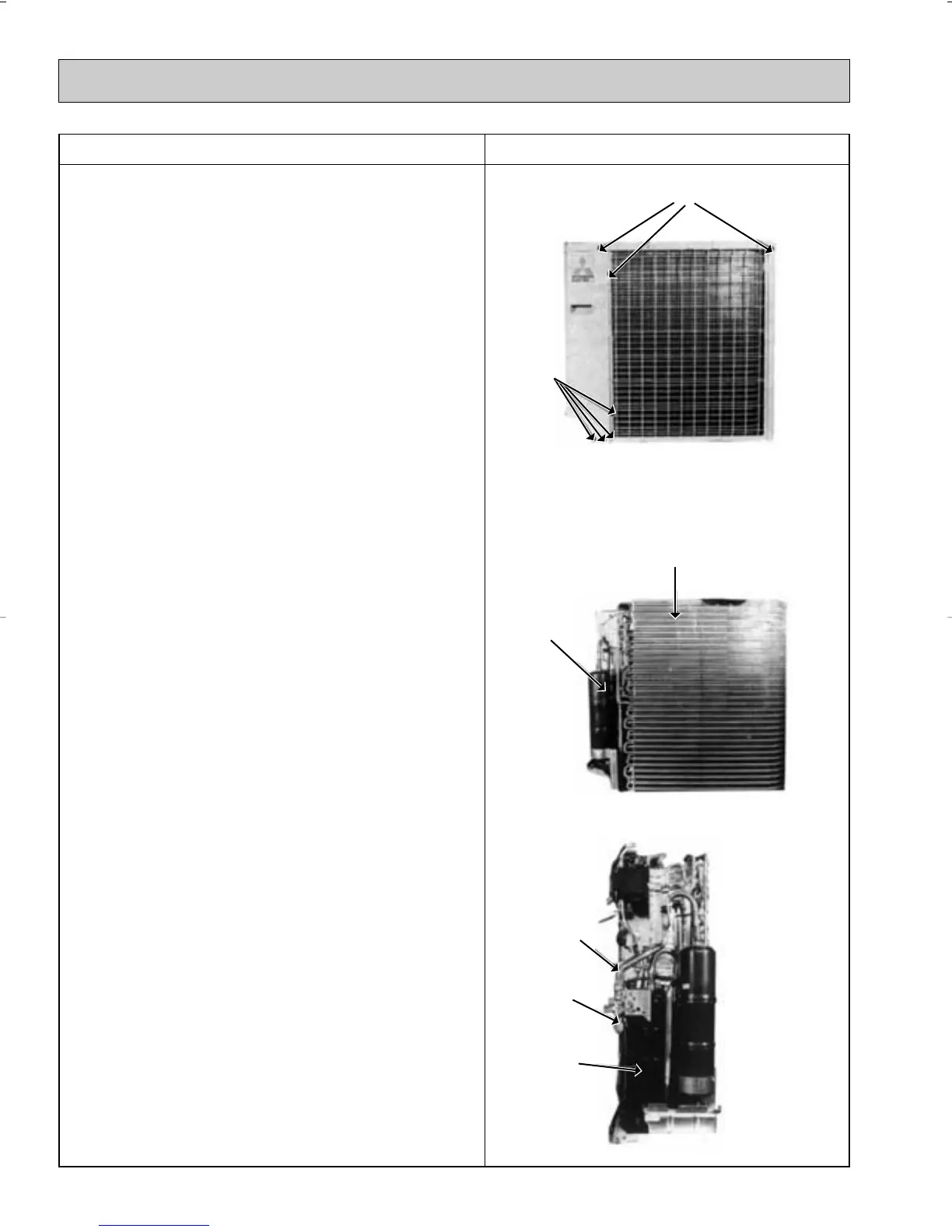
3. Heat Exchanger, Compressor
(1) Remove the rear panel (2 screws in front, 1 screw on the
side, 3 screws in the rear). Remove the valve bed, and open
the rear panel to the rear to remove.
(2) Remove right side panel (4 screws).
(3) Remove rear guard (3 screws).
(4) Remove separator support plate (4 screws).
(5) Remove motor support (2 screws).
(6) Remove valve bed (5 screws). The valve bed is clasped on
the right and left sides. Lift to remove.
(7) Remove the electrical parts box.
Remove the respective connector from high pressure
switch, crank case heater, outdoor coil thermistor and fan
motor lead.
(8) Remove separator (2 screws).
(9) Remove heat exchanger (2 screws).
Disconnect the welded section of pipe.
(10) Remove compressor (3 set nuts).
Remove the weldment of the compressor suction pipe and
discharge pipe.
Photo 4
Heat exchanger
Accumulator
Photo 5
Charge plug
Ball valve
Compressor
Photo 6
OC247-E--1.qxp 04.8.11 4:25 PM Page 26
 Loading...

