EasyManua.ls Logo

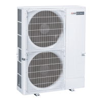
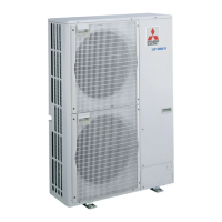
Mitsubishi PUY-A36NHA6 User Manual

Mitsubishi PUY-A36NHA6
128 pages
To Next Page IconTo Next Page
Page #1 background imageLoading...
Page #1 background image
SERVICE MANUAL
CONTENTS
1. REFERENCE MANUAL ································· 2
2. SAFETY PRECAUTION ································· 2
3. FEATURES ····················································· 6
4. SPECIFICATIONS ·········································· 7
5. DATA ······························································· 9
6. OUTLINES AND DIMENSIONS ··················· 13
7. WIRING DIAGRAM ······································ 16
8. WIRING SPECIFICATIONS ·························· 20
9.
REFRIGERANT SYSTEM DIAGRAM
············· 23
10. TROUBLESHOOTING ·································· 26
11. EASY MAINTENANCE FUNCTION·············· 91
12. FUNCTION SETTING ··································· 95
13.
MONITORING THE OPERATION DATA BY THE REMOTE CONTROLLER
···105
14. DISASSEMBLY PROCEDURE ··················· 114
R410A
Outdoor unit
[Model Name]
PUZ-A18NHA6
PUZ-A24NHA6
PUZ-A30NHA6
PUZ-A36NHA6
PUZ-A42NHA6
PUZ-A18NHA6-BS
PUZ-A24NHA6-BS
PUZ-A30NHA6-BS
PUZ-A36NHA6-BS
PUZ-A42NHA6-BS
PUY-A12NHA6
PUY-A18NHA6
PUY-A24NHA6
PUY-A30NHA6
PUY-A36NHA6
PUY-A42NHA6
PUY-A12NHA6-BS
PUY-A18NHA6-BS
PUY-A24NHA6-BS
PUY-A30NHA6-BS
PUY-A36NHA6-BS
PUY-A42NHA6-BS
[Service Ref.]
PUZ-A18NHA6
PUZ-A24NHA6
PUZ-A30NHA6
PUZ-A36NHA6
PUZ-A42NHA6
PUZ-A18NHA6-BS
PUZ-A24NHA6-BS
PUZ-A30NHA6-BS
PUZ-A36NHA6-BS
PUZ-A42NHA6-BS
PUY-A12NHA6
PUY-A18NHA6
PUY-A24NHA6
PUY-A30NHA6
PUY-A36NHA6
PUY-A42NHA6
PUY-A12NHA6-BS
PUY-A18NHA6-BS
PUY-A24NHA6-BS
PUY-A30NHA6-BS
PUY-A36NHA6-BS
PUY-A42NHA6-BS
PUZ-A24/30/36NHA6
PUY-A24/30/36NHA6
PARTS CATALOG (OCB577)
Notes:
•Thismanualdescribesservice
dataoftheoutdoorunitsonly.
•
RoHScompliantproductshave
<G>markonthespecname
plate.
SPLIT-TYPE,HEATPUMPAIRCONDITIONERS
SPLIT-TYPE,AIRCONDITIONERS
August 2015
No. OCH577
REVISED EDITION-A
•PleasevoidOCH577.
Revision:
•Updatedthetablein
"1.REFERENCEMANUAL"
in
REVISEDEDITION-A.
•Somedescriptionshavebeen
modified.
Question and Answer IconNeed help?

Do you have a question about the Mitsubishi PUY-A36NHA6 and is the answer not in the manual?

Mitsubishi PUY-A36NHA6 Specifications

General IconGeneral
BrandMitsubishi
ModelPUY-A36NHA6
CategoryAir Conditioner
LanguageEnglish

Summary

REFERENCE MANUAL

SAFETY PRECAUTION

2-1. ALWAYS OBSERVE FOR SAFETY

General safety guidelines before and during repair.

WIRING DIAGRAM

WIRING SPECIFICATIONS

REFRIGERANT SYSTEM DIAGRAM

TROUBLESHOOTING

10-1. TROUBLESHOOTING

General troubleshooting based on recurring or non-recurring issues.

10-2. CHECK POINT UNDER TEST RUN

Key points to check before performing a test run.

10-2-1. Test run for wired remote controller <PAR-30MAA> <PAR-31MAA>

Detailed steps for performing a test run using the remote controller.

Test run [for IR wireless remote controller]

Procedure for conducting a test run using the IR wireless remote controller.

10-3. HOW TO PROCEED "SELF-DIAGNOSIS"

Steps for performing self-diagnosis using the remote controller.

Remote controller check <PAR-30MAA> <PAR-31MAA>

Procedure to diagnose and check the remote controller's function.

10-4. SELF-DIAGNOSIS ACTION TABLE

Table of abnormalities detected at power-on and corresponding actions.

Check code Abnormal point and detection method

Details specific error codes, their causes, and recommended actions.

<Abnormalities detected while unit is operating>

Lists abnormalities detected during operation and their troubleshooting steps.

HOW TO CHECK THE PARTS

Instructions for checking the resistance of various components.

Circuit Board Checks

Guides for checking circuit boards, filters, power supplies, and modules.

Emergency Operation

Procedures and data for emergency operation under specific abnormal conditions.

TEST POINT DIAGRAMS

Diagrams showing test points on various circuit boards for diagnosis.

FUNCTION OF SWITCHES, CONNECTORS AND JUMPERS

Explains the function of switches, connectors, and special functions.

EASY MAINTENANCE FUNCTION

11-1. SMOOTH MAINTENANCE

Procedure for smooth maintenance to display operational data.

11-3. INITIAL SETTINGS FOR REFRIGERANT LEAKAGE DETECTION FUNCTION

Initial setup for refrigerant leakage detection.

FUNCTION SETTING

12-1. UNIT FUNCTION SETTING BY THE REMOTE CONTROLLER

How to set unit functions using the remote controller.

MONITORING THE OPERATION DATA BY THE REMOTE CONTROLLER

DISASSEMBLY PROCEDURE

Related product manuals