105
OPERATING PROCEDURE
PHOTOS
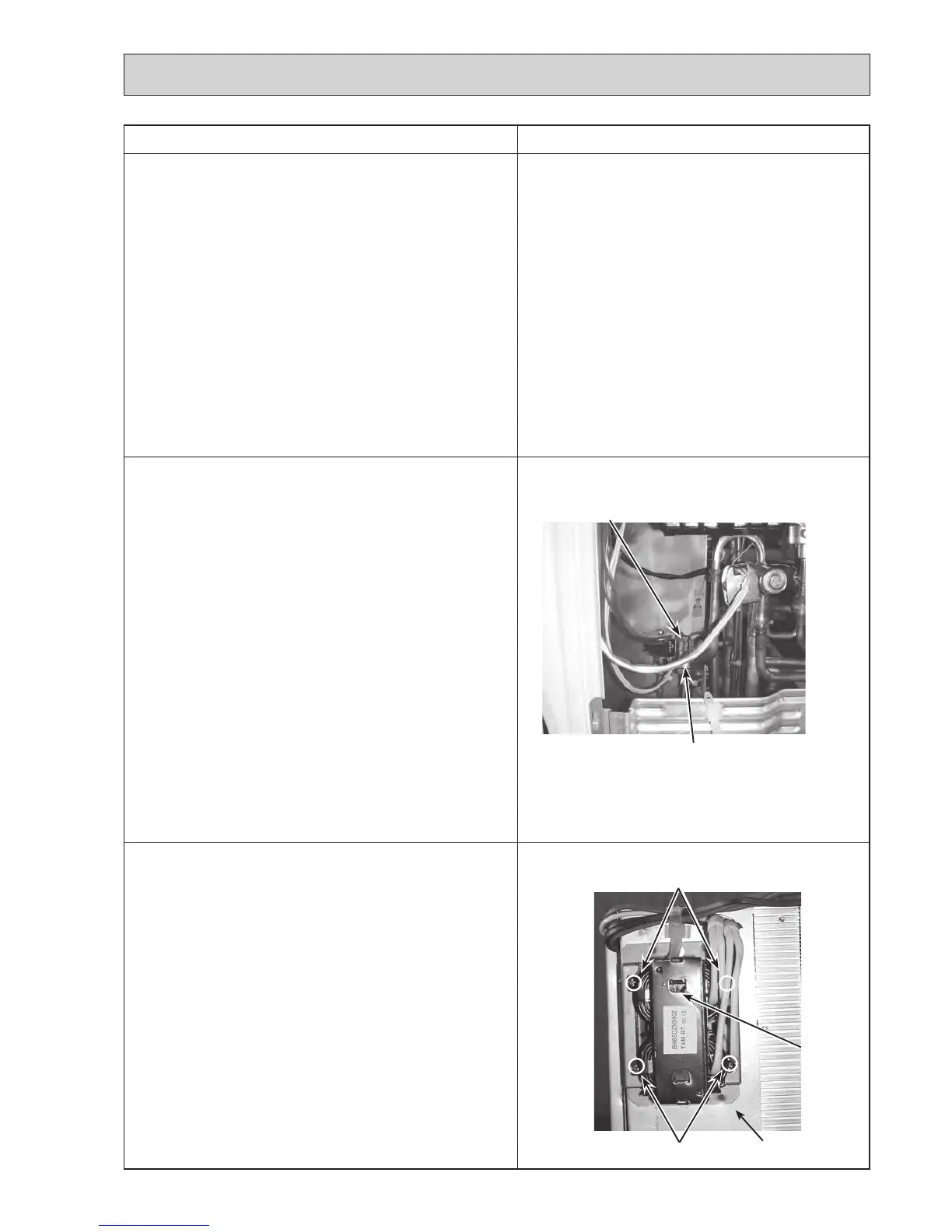
11. Removing the reactor (DCL)
(1) Remove the service panel. (See Figure 1)
(2) Remove the top panel. (See Figure 1)
(3) Remove the electrical parts box. (Refer to procedure 3)
(4) Remove 4 reactor fixing screws (4 × 10) and remove the
reactor.
Note: The reactor is attached to the rear of the electrical parts
box.
Photo 9
10. Removing the high pressure switch (63H)
(1) Remove the service panel. (See Figure 1)
(2) Remove the top panel. (See Figure 1)
(3) Remove the electrical parts box if necessary
(Refer to procedure 3)
(4) Remove the cover panel (front). (See Figure 2)
(5) Remove cover panel (rear). (See Figure 2)
(6) Remove the valve bed. (Refer to procedure 8)
(7) Remove the side panel (R). (Refer to procedure 8)
(8) Pull out the lead wire of high pressure switch.
(9)
Disconnect the lead wire of 63H (Yellow) on the controller
circuit board.
(10) Remove the electrical parts box. (Refer to procedure 3)
(11) Loosen the clamp on the separator and unbind the lead
wires.
(12) Recover refrigerant.
(13) Remove the welded part of high pressure switch.
Note 1: Recover refrigerant without spreading it in the air.
Note 2: The welded part can be removed easily by
removing the right side panel.
Note 3: When installing the high pressure switch, cover it
with a wet cloth to prevent it from heating (100°C
or more), then braze the pipes so that the inside
of pipes are not oxidized.
Photo 10 (PUHZ-SP100VHA)
Reactor fixing screw
Reactor fixing screws
Reactor
(DCL)
Electrical parts box
Lead wire of
high pressure switch
High pressure switch (63H)
9. Removing the LEV
(1) Remove the service panel. (See Figure 1)
(2) Remove the top panel. (See Figure 1)
(3) Remove the electrical parts box. (Refer to procedure 3)
(4) Remove the cover panel (front). (See Figure 2)
(5) Remove cover panel (rear). (See Figure 2)
(6) Remove the valve bed. (Refer to procedure 8)
(7) Remove the side panel (R). (Refer to procedure 8)
(8) Remove the LEV coil. (See Photo 7)
(9) Recover refrigerant.
(10) Remove the welded part of LEV.
Note 1: Recover refrigerant without spreading it in the air.
Note 2: The welded part can be removed easily by
removing the right side panel.
Note 3: When installing the LEV, cover it with a wet cloth
to prevent it from heating (120°C or more), then
braze the pipes so that the inside of pipes are not
oxidized.

 Loading...


