67
Brief Check of POWER MODULE
Usually, they are in a state of being short-circuited if they are broken.
Measure the resistance in the following points (connectors, etc.).
If they are short-circuited, it means that they are broken.
1. Check of DIODE MODULE
L1 - P1 , L2 - P1 , L3 - P1 , L1 - N1 , L2 - N1 , L3 - N1
2. Check of DIP-IPM
P2 - U , P2 - V , P2 - W , N2 - U , N2 - V , N2 - W
Note: The marks L1 , L2 , L3 , N1 , N2 , P1 , P2 , U , V and W
shown in the diagram are not actually printed on the board.
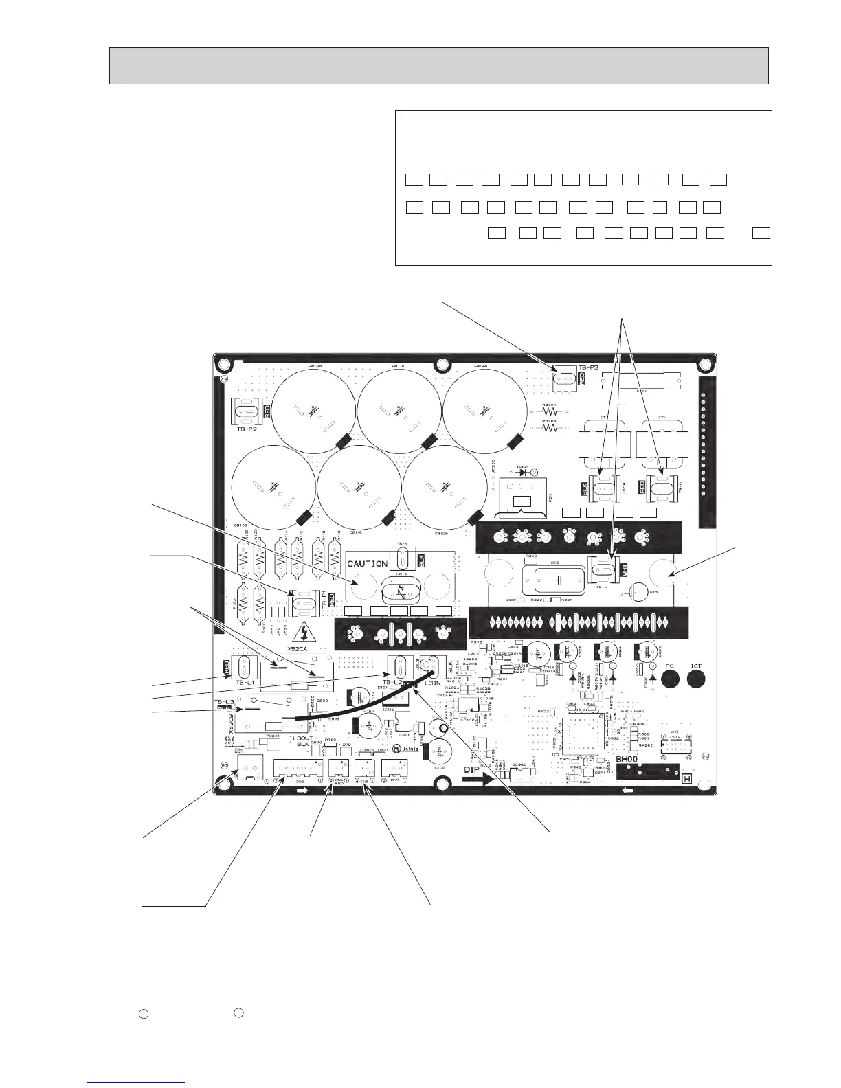
Outdoor power circuit board
PUHZ-SP100YHA.UK
CN5
Detection of primary
current (Connect to
the outdoor noise filter
circuit board (CNCT))
CN4
Connect to the
outdoor controller
circuit board (CN4)
CN2
Connect to the outdoor controller circuit board (CN2)
1–5: Power circuit board
→ Transmitting
signal to the controller board (0–5 V DC)
2–5: Zero cross signal (0–5 V DC)
3–4: Not used
6–5: 16 V DC
7–5: 16 V DC
[ 5 : – 1, 2, 6, 7 : + ]
TB-U, TB-V, TB-W
Connect to the compressor (MC)
Voltage among phases:
10–400 V AC
TB-P3
Connect to the DCL
Diode module
U P2VW
N2
L3 N1L1P1 L2
DIP-IPM
TAB connector
on X52CA
Connect to the
RS resistor
CN6
Thermistor
<Heat sink> (TH8)
TB-L1,
TB-L2,
TB-L3
Connect to the
outdoor noise
filter circuit board
(LO1, LO2, LO3)
400 V AC
L3OUT-L3IN
Lead connect
TB-P1
Connect to the DCL

 Loading...


