114
OPERATING PROCEDURE PHOTOS
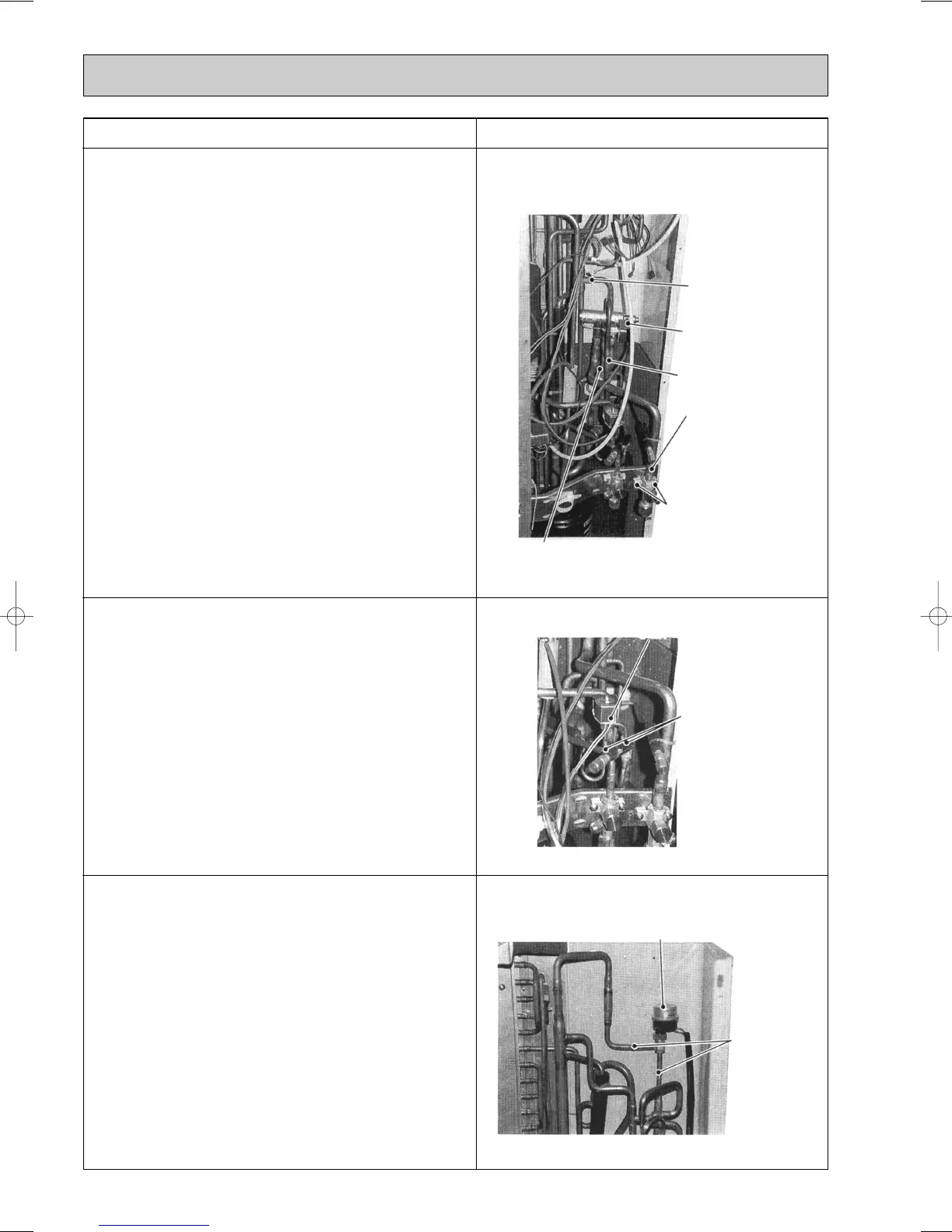
9. Four-way valve disassembly procedures:
(1) Remove the side panel (Refer to 1).
(2) Remove the top panel (Refer to 1).
(3) Remove the electrical box (Refer to 4).
(4) Remove the 4-way valve coil (Refer to 5).
(5) Remove the mounting screws from the gas side ball
valve (2 pcs : 5o16).
(6) Remove the field piping from the outdoor unit (gas side).
(7) Remove the welded portion.
1 Upper and lower heat exchanger inlet (T connector).
2 Accumulator inlet (T connector)
3 4-way valve inlet
(8) Remove 4-way valve.
✻
Do not expose 4-way valve to above 120°C.
Photo 9
Photo 10
Photo 11
10. Solenoid valve disassembly procedures:
(1) Remove the side panel (Refer to 1).
(2) Remove the electrical box (Refer to 4).
(3) Remove the solenoid valve coil (Refer to 5).
(4) Remove the welded portions of the solenoid valve.
(take care excessive heating)
11. Electronic expansion valve disassembly procedures:
(1) Remove the side panel (Refer to 1).
(2) Remove the electrical box (Refer to 4).
(3) Remove welded portions of expansion valve.
(take care excessive heating)
Heat exchanger inlet
(T connector)
Accumulator inlet (T connector)
Fixing screws
Gas side ball valve
4-way valve inlet
4-way valve
Solenoid valve coil
Welding part
Expansion valve
Welding part
OC183E--4.qxp 10.5.6 0:54 PM Page 114
 Loading...


