Only PUMY-125VMA1
9
8
7
6
5
4
3
2
1
0
9
8
7
6
5
4
3
2
1
0
Switch(Function Selection)SW6
2
2
ACTM
< M.B.>
< N.F.>
< P.B.>
LED1
1
3
1
3
1
3
7
*1
*1 The address automatically
becomes "100" if it is
set as "01~50".
POWER SUPPLY
~ / N
220-230-240V
NO FUSE BREAKER 32A
TO INDOOR UNIT
CONNECTING WIRES
DC 30V (Non-polar)
FOR CENTRALIZED
CONTROL
DC 30V (Non-polar)
CE
+
52C
RS
N
L
TB1
L
N
M1
M2
S
TB7
ORN
ORN
S
M2
M1
BRN
BRN
TB3
DCL3
L2
L1
DCL2 DCL1
DCL4
DCL1DCL2
L1
+
-
N1
N2
I
P
652341
L2
EI
CN5
(RED)
21
CNAC2
(RED)
31
NI
LI
NO
LO
MC
BLK
WHT
RED
743215
CN2 (WHT)
66
CNAF (WHT)
51234
(PNK)
CNDC
THHS-B
1
2
1
2
THHS-A
CN6
(WHT)
(RED)
CN5
CN4
(WHT)
1
2
1
2
CN3
(WHT)
13
SCR-N1
SCR-P1
U
V
W
+
-
-
+
+
SCR-R
SCR-S
SCR-P2
SCR-N2
IGBT
YLW YLW
49C
6
131432567
LEV
13 13
(WHT)
MF2
MF2
31
BLU
WHT
WHT
BLU
31
BLU
WHT
WHT
BLU
RED
ORN
C2
RED
ORN
C1
MF1
(WHT)
MF1
F.C
F1
(6.3A) (6.3A)
F2
(RED)
CNAC
31
X502
CH(BLU)
X501
X500
SV(BLK)
SV1
BLK
BLK
21S4(GRN)
21S4
BLU
BLU
YLW
YLW
52C(ORG)
1
3
52C
CNDC(PNK)
1
2
3
1
1
1
2
1
2
1
2
CN2 (WHT)
63HS
TH2
TH5
TH6
TH1
(RED)
TH2
(GRN)
TH5
TH1
(WHT)
(WHT)
TH6
63HS
(WHT)
1234 1234
CN40(WHT)CN41(WHT)
(WHT)
CN51
3.12V
4.COMP. ON
5.Error
1
CN4
(WHT)
2
SW4
4321
OFF
ON
5
4
3
2
1
CNS2
CNS1
(YLW)
1
2
(RED)
CN3D(WHT)
321
CN3S(WHT)
321
49C/26C
(GRY)
31
1
LEV-A (WHT)
65432
SW3
1 3456782
OFF
SW6
ON
OFF
ON
21
SW5
OFF
ON
LED2LED1
ON
OFF
SW2
12345678910
OFF
ON
1
SW1
345678213456782
(1st digit)(2nd digit)
SWU2 SWU1
LED1,2
Digital Indication LED
Operation Inspection Indication
X502
Relay(Solenoid Valve)
X501
Relay(4-Way Valve)
X500
Relay(Magnetic Contactor)
CN3S
Connector(Connected for Option)
Demand Signal
CN3D
Auto Change Over Signal
Connector(Connected for Option)
Compressor drive signal,Error signal
Connector(Connected for Option)
CN51
CN41
Connector(For String Jumper Connector)
CN40
Connector(Centralized Control Power Supply)
CN4
Connector
CNS2
Connector(Centralized Control)
Connector(Multi system)
CNS1
Switch(Unit Address Selection,2nd digit)
Switch(Unit Address Selection,1st digit)
SWU2
SWU1
OFF;disabled ON;enabled
SW5-1 Auto Change Over
Switch(Function Selection)
Switch(Model Selection)
Switch(Test Run)
Switch(Function Selection)
SW5
SW4
SW3
SW2
SW1 Switch(Display Selection)
Fuse(6.3A)
F1,F2
Multi Circuit BoardM.B.
Connector
Connector
CN5
CNAC2
Connection Terminal(Ground)
EI
NI/NO
Connection Lead(N-Phase)
LI/LO
Connection Lead(L-Phase)
Noise Filter Circuit BoardN.F.
SC-N1,N2
SC-P1,P2
Screw Type Terminal(DC Voltage)
Screw Type Terminal(DC Voltage)
SC-S,R
LED1
IGBT
Connector
CNAF
Connector
CNDC
CN2~6
Connection Terminal(U/V/W Phase)
U/V/W
P.B. Power Circuit Board
Thermal Switch(Compressor)49C
Thermistor(Radiator Panel) A;ACTM,B;IGBT
Thermistor(Outdoor Temp.Detection)
TH5
Thermistor (Pipe Temperature
Detection / Judging Defrost)
Reactor(PUMY-125VMA)
Reactor(PUMY-125 VMA
1)
Fan Motor Capacitor
Smoothing Capacitor
Terminal Block(Centralized Control)
TB7
Terminal Block(Transmission)TB3 4-Way Valve21S4
Connector
Fan Motor(Inner Thermostat)
Compressor(Inner Thermostat)
MF1,MF2
SV
MC
DCL1~4
DCL1,2
C1,C2
Solenoide Valve(Hot Gas Bypass)
TH6
TB1 Terminal Block(Power Supply)
RS
Resistor(Rush Current Protection)
ACTM Active Filter Module
TH1
Thermistor(Discharge Temperature Detection)
TH2
Thermistor (Low Pressure
Saturated Temperature Detection)
LEV(A) Expansion Valve
Magnetic Contactor52C
Light Emitting Diode(Inverter Control Status)
Screw Type Terminal(L./N-Phase)
Converter, Inverter
CE
63HS
(Discharge Pressure Detection)
High Pressuer Sensor
THHS A/B
operated
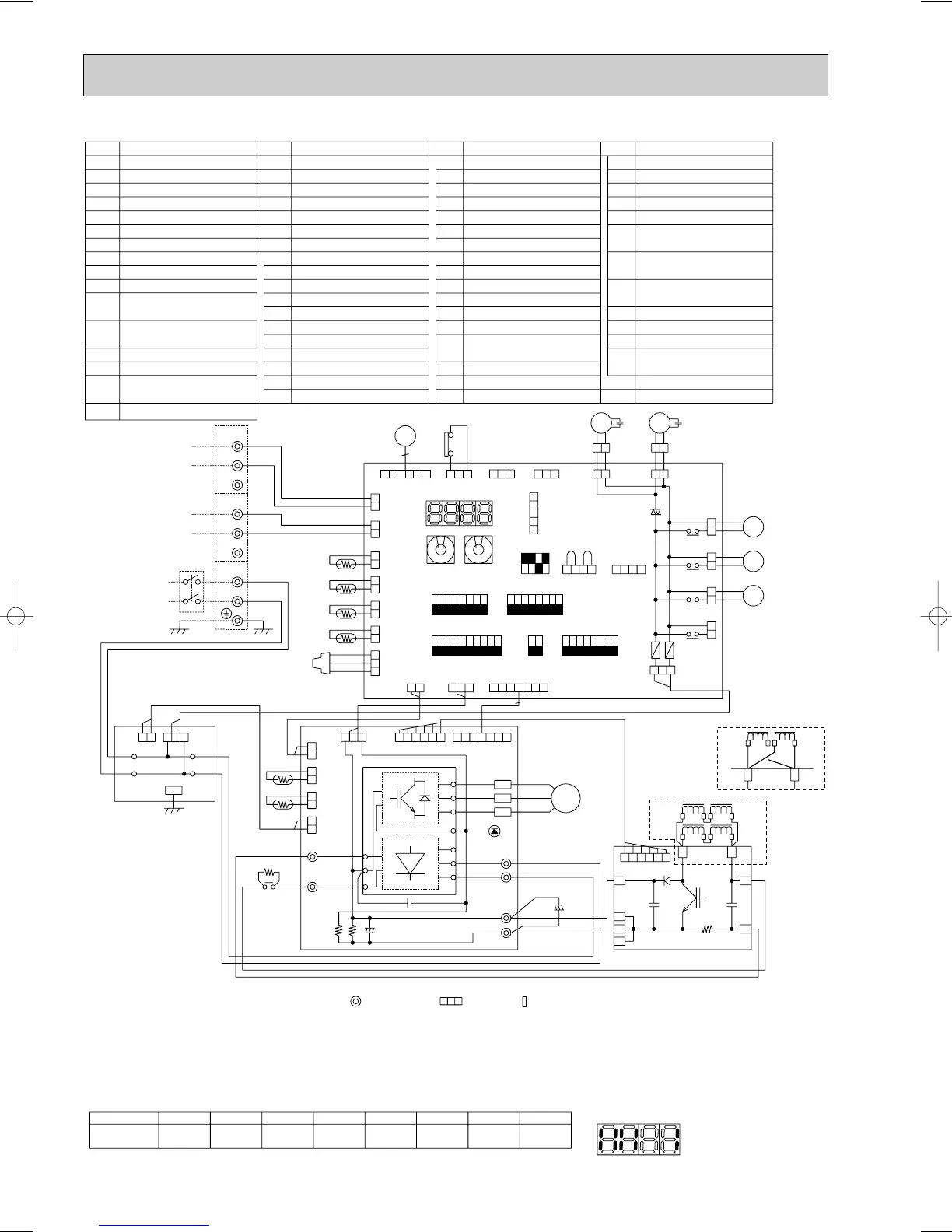
NOTES: 1. Refer to the wiring diagrams of the indoor units for details on wiring of each indoor unit.
2. Symbols used in wiring diagram above are. :Terminal block, :Connector, :Insertion tab.
3. Self-diagnosis function
The indoor and outdoor units can be diagnosed automatically using the self-diagnosis switch(SW1) and LED1,2
(LED indication)found on the multi-controller of the outdoor unit.
LED indication : Set all contacts of SW1 to OFF.
4. The input for CN3D 1-2(AUTO CHANGE OVER EXTERNAL SIGNEL)is as follows.
Short;heating Open;Cooling(It differs from Service ref.PUMY-(P)125YMA)
7
8
5
6
3
42
1
(Example)
When the compressor and SV1 are
turned during cooling operation.
Always lit---SV121S4
1 876543
52C
2
Compressor
Indication
Bit
•During normal operation
The LED indicates the drive state of the controller in the outdoor unit.
•When fault requiring inspection has occurred
The LED alternately indicates the inspection code and the location of the unit in which the fault has occurred.
SYMBOL
NAME
SYMBOL
NAME
SYMBOL
NAME
SYMBOL
NAME
 Loading...


