M
Blue
Brown
Yellow
Orange
Red
White
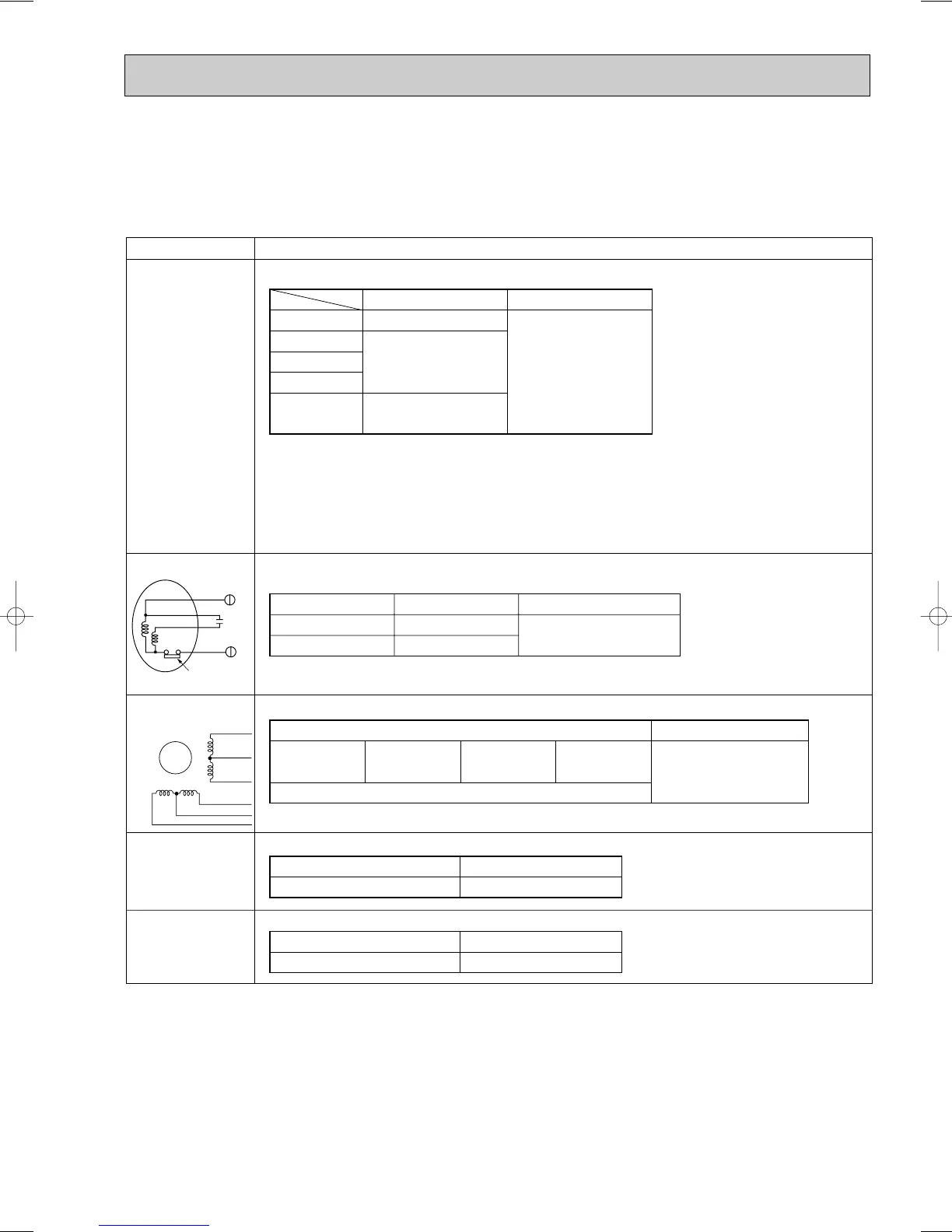
Parts name
Check points
Disconnect the connector then measure the resistance using a tester. (Surrounding temperature 10:~30:)
Disconnect the connector then measure the resistance using a tester. (
Part wiring temperature
20:)
•Thermistor (TH1)
<Discharge temperature detection>
•Thermistor (TH2)
<Low pressure saturated
temperature detection>
•Thermistor (TH5)
<Pipe temperature
detection / judging defrost>
•Thermistor (TH6)
<Outdoor temperature detection>
•Thermistor (THHS A/B)
<Radiator panel>
PUMY-125VMA, VMA
1
•Thermistor (THHS)
<IPM radiator panel
temperature thermistor
detection>
PUMY-71VM,VM
1,VM2
PUMY-125VM,VM1,VM2
PUMY-125YM,YM1
PUMY-125YMA
Normal
160k"~410k"
4.3k"~9.6k"
TH1
TH2
TH5
TH6
Abnormal
Open or short
Measure the resistance between the terminals using a tester. (Part wiring temperature 20C°)
4-way coil
w2
(21S4)
Normal
1434"
Normal
White - Red Yellow - Brown Orange - Red Blue - Brown
Abnormal
Abnormal
150" ±10%
Open or short
Normal
1500"
Abnormal
Open or short
Open or short
Measure the resistance between the terminals using a tester. (Part wiring temperature 20C°)
Solenoid coil
w3
(SV1)
Measure the resistance between the terminals using a tester.
(Part wiring temperature 20C°)
Expansion valve
(SLEV w1)
Only PUMY-125VMA model w1 LEV(A)
w2 4-way valve (21S4)
w3 Solenoid valve (SV)
Fan motor (MF1,2)
Normal
107.5" ±10%
128.0" ±10%
Motor lead wire
Abnormal
Open or short
White — Blue
Blue — Red
Red
White
Blue
Orange
Protector
Opening and closing temperature of protector.
Open: 135i5°C (Fan motor OFF)
Close: 86i15°C (Fan motor ON)
THHS A/B
THHS
39k"~105k"
8-7. HOW TO CHECK THE PARTS
 Loading...


