96
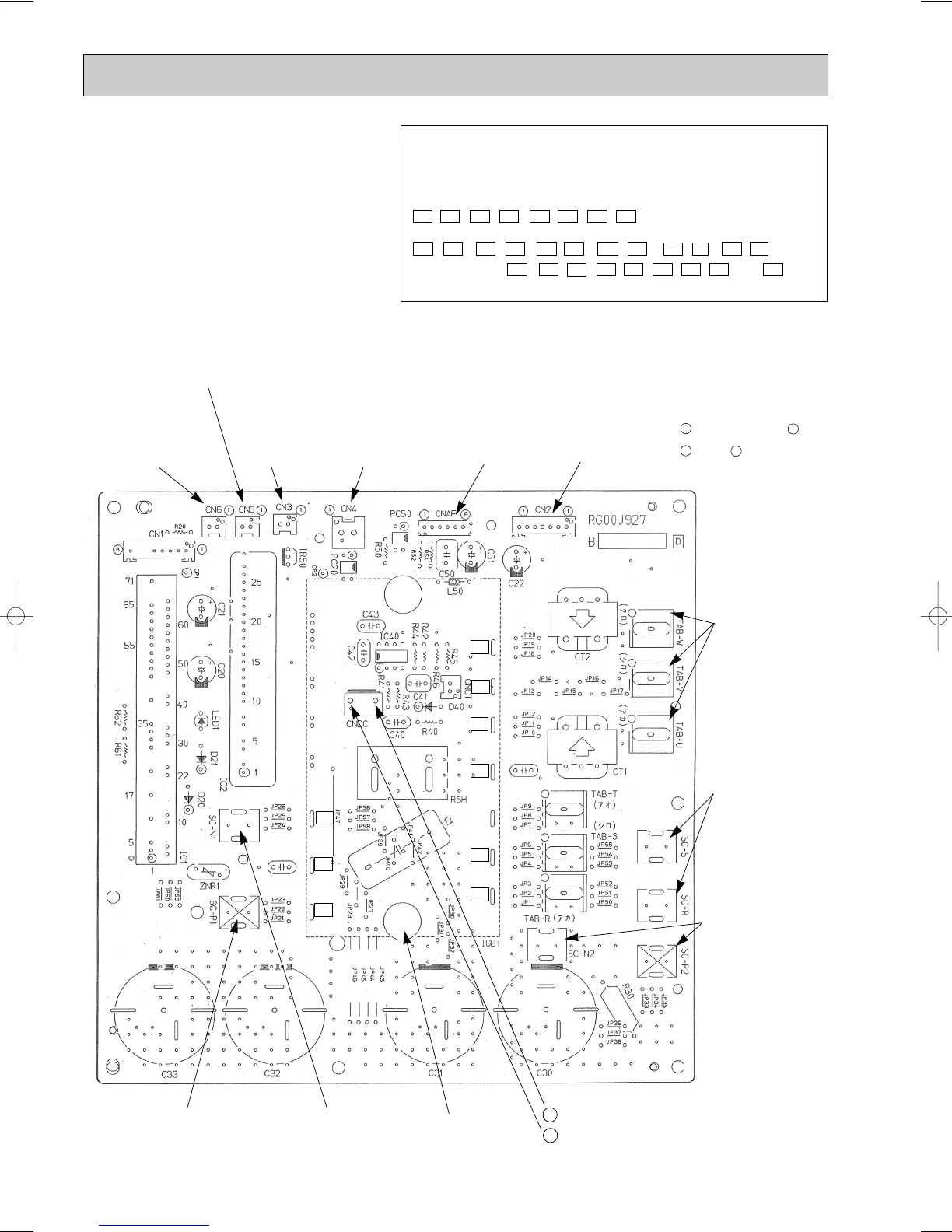
8-8-6. Outdoor power circuit board
PUMY-125VMA
PUMY-125VMA1
CNAF
Connect to
ACTM
SC-P2, SC-N2
Connect to
ACTM and the
smoothing
capacitor
SC-P1
Connect to 52C
SC-N1
Connect to
ACTM (–)
–
+
}
Brief Check of POWER MODULE
W Usually, they are in a state of being short-circuited if they are broken.
Measure the resistance in the following points (connectors, etc.).
If they are short-circuited, it means that they are broken.
1. Check of POWER MODULE
1.Check of DIODE circuit
L - P1 , N - P1 , L - N1 , N - N1
2.Check of IGBT circuit
P2 - U , P2 - V , P2 - W , N2 - U , N2 - V , N2 - W
Note:The marks, L , N , N1 , N2 , P1 , P2 , U , V and W
shown in the diagram above are not actually printed on the board.
POWER
MODULE
CNDC
300V-380V DC
Connect to the outdoor multi
circuit board (CNDC)
P1
P2
N1
L
N
N2
U
V
W
CN5
Detection of primary current
(Connect to the outdoor noise
filter circuit board (CN5))
CN3
Temperature
(Radiator panel
(THHS-A))
CN4
Connect to the
outdoor controller
circuit board
(CN4)
TAB-U, TAB-V,
TAB-W
Connect to the
compressor (MC)
Voltage among
phases:
5V-180V AC
SC-R, SC-S
Connect to the
outdoor noise filter
circuit board
(LO, NO)
220V-240V AC
CN2
Connect to the outdoor multi circuti board (CN2)
1-5: Power circuit board
➔ Transmitting
signal to the controller board (0-5V DC)
2-5: Zero cross signal (0-5V DC)
3-4: 18V DC
6-5: 15V DC
7-5: 15V DC
[ 5 : – 1, 2, 6, 7 : + ]
[ 4 : – 3 : + ]
CN6
Temperature
(Radiator panel
(THHS-B))
OC183E--4.qxp 10.5.6 0:54 PM Page 96
 Loading...


