10
5. Drainage piping work
4. Installing the refrigerant piping
Outdoor unit drainage pipe connection
When drain piping is necessary, use the drain socket or the drain pan (option).
Drain socket PAC-SG61DS-E
Drain pan PAC-SH97DP-E
6. Electrical work
Fig. 4-9
4.6. Stop valve opening method
Thestopvalveopeningmethodvariesaccordingtotheoutdoorunitmodel.Usethe
appropriate method to open the stop valves.
(1) Gas side (Fig. 4-7)
1 Remove the cap, pull the handle toward you and rotate 1/4 turn in a counterclock-
wise direction to open.
2 Make sure that the stop valve is open completely, push in the handle and rotate
the cap back to its original position.
(2) Liquid side (Fig. 4-8)
1 Remove the cap and turn the valve rod counterclockwise as far as it will go with
the use of a 4 mm [3/16"] hexagonal wrench. Stop turning when it hits the stopper.
2 Make sure that the stop valve is open completely and rotate the cap back to its
original position.
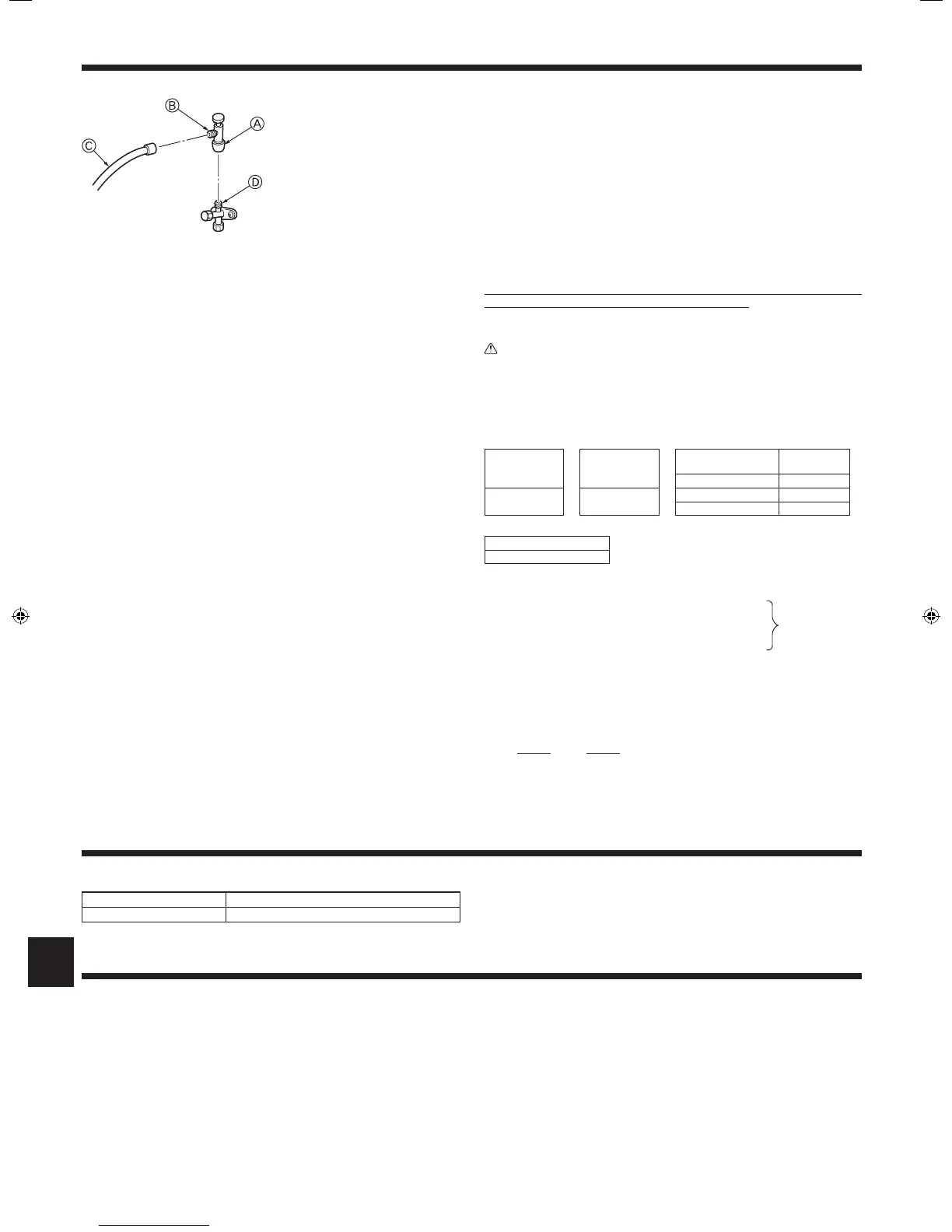
Precautions when using the charge valve (Fig. 4-9)
Do not tighten the service port too much when installing it, otherwise, the valve core
could be deformed and become loose, causing a gas leak.
After positioning section B in the desired direction, turn section A only and tighten it.
Do not further tighten sections A and B together after tightening section A.
Warning:
• When installing the unit, securely connect the refrigerant pipes before
starting the compressor.
6.1. Caution
1 Follow ordinance of your governmental organization for technical standard
related to electrical equipment, wiring regulations and guidance of each electric
power company.
2 Wiring for control (hereinafter referred to as transmission line) shall be (5 cm
[2inch]ormore)apartfrompowersourcewiringsothatitisnotinuencedby
electric noise from power source wiring. (Do not insert transmission line and
power source wire in the same conduit.)
3 Be sure to provide designated grounding work to outdoor unit.
4 Give some allowance to wiring for electrical part box of indoor and outdoor
units, because the box is sometimes removed at the time of service work.
5 Neverconnectthemainpowersourcetoterminalblockoftransmissionline.If
connected, electrical parts will be burnt out.
6 Use2-coreshieldcablefortransmissionline.Iftransmissionlinesofdifferent
systems are wired with the same multiplecore cable, the resultant poor trans-
mitting and receiving will cause erroneous operations.
7 Onlythetransmissionlinespeciedshouldbeconnectedtotheterminalblock
for outdoor unit transmission.
(Transmission line to be connected with indoor unit : Terminal block TB3 for
transmission line, Other : Terminal block TB7 for centralized control)
Erroneous connection does not allow the system to operate.
8 In case to connect with the upper class controller or to conduct group operation
in different refrigerant systems, the control line for transmission is required
between the outdoor units each other.
Connect this control line between the terminal blocks for centralized control.
(2-wire line with no polarity)
When conducting group operation in different refrigerant systems without con-
necting to the upper class controller, replace the insertion of the short circuit
connectorfromCN41ofoneoutdoorunittoCN40.
9 Before turning outdoor unit on, be sure to turn the indoor units and the branch
boxes.
* Theguretotheleftisanexample
only.
The stop valve shape, service port
position, etc., may vary according to
the model.
* Turn section A only.
(Do not further tighten sections A and
B together.)
C Charge hose
D Service port
4.7. Additional refrigerant charge
Additional refrigerant charge
Refrigerant for the extended piping is not included in the outdoor unit when the unit is
shipped from the factory. Therefore, charge each refrigerant piping system with addi-
tional refrigerant at the installation site. In addition, in order to carry out service, enter
the size and length of each liquid pipe and additional refrigerant charge amounts in
the spaces provided on the “Refrigerant amount” plate on the outdoor unit.
Calculation of additional refrigerant charge
• Calculatetheadditionalchargeusingtheliquidpipesizeandlengthoftheex-
tended piping and total capacity of connected indoor units.
• Calculatetheadditionalrefrigerantchargeusingtheprocedureshowntothe
right, and charge with the additional refrigerant.
• Foramountslessthan0.1kg,roundupthecalculatedadditionalrefrigerant
charge.
(For example, if the calculated charge is 6.01 kg, round up the charge to 6.1 kg.)
<Example>
Outdoormodel : PUMY-P48NKMU1
Indoor 1: model24 A: ø9.52 30m a:ø9.52 15m(49ft)
2: model15 b:ø6.35 10m(33ft)
3: model08 c:ø6.35 10m(33ft)
4: model08 d:ø6.35 20m(66ft)
The total length of each liquid line is as follows:
ø9.52:A+a=30+15=45m(148ft)
ø6.35:b+c+d=10+10+20=40m(131ft)
The total capacity of connected indoor unit is as follows:
24 + 15 + 08 + 08 = 55
<Calculationexample>
Additional refrigerant charge
40 ×
19.0
+ 45 ×
50.0
+ 3.0 = 6.1 kg (rounded up)
1000 1000
(131 × 0.21 + 148 × 0.55 + 106 = 215 oz)
<Additional Charge>
Calculation of refrigerant charge
Pipe size
Liquid pipe
+
Pipe size
Liquid pipe
+
Total capacity of
connected indoor units
Amount for the
indoor units
ø6.35 ø9.52 –27 1.5 kg (53 oz)
(m) × 19.0 (g/m)
(0.21 (oz/ft))
(m) × 50.0 (g/m)
(0.55 (oz/ft))
28–54 2.5 kg (88 oz)
55–62 3.0 kg (106 oz)
Included refrigerant amount when shipped from the factory
Included refrigerant amount
4.8 kg (169 oz)
At the conditions
below:
RG79F079H01_EN.indd 10 2/24/2016 2:57:22 PM

 Loading...


