12
6. Electrical work
6.4. Wiring of main power supply and equipment capacity
Schematic Drawing of Wiring (Example) (Fig. 6-4)
A : Switch (Breakers for Wiring and Current Leakage)
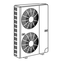
B :OutdoorUnit
C : Pull Box
D :IndoorUnit
Fig. 6-4
D D
C
A
D D
A
B
C
E
D
TB7
TB3
IC
(51)
TB5
RC
(01)
IC
TB5
(03)
IC
TB5
(02)
IC
TB5
(04)
IC
TB5
(05)
IC
TB5
(07)
IC
TB5
(06)
L
2
L1
(101)
RC
(105)
RC
(104)
RC
(155)
OC
TB7
(53)
OC
DC24V
3
Power Supply
Unit
System
controller
L
3
L
6
L7
L
4
L
5
2
4
1
F
r
r
r
r
M1 M2
S
M1 M2
S
M1 M2
S
M1 M2
S
A BA BA B
M1 M2
S
M1 M2
S
M1 M2
S
S
M1 M2
S
TB3
M1 M2
S
M1 M2
S
A B
M1 M2
M1 M2
S
M1 M2
S
F
A
B
C
E
D
TB7
IC
(51)
TB15 TB15
TB15
MA
(01)
IC
TB5
(03)
IC
TB5TB5
(02)
IC
TB5
(04)
IC
(05)
IC
(07)
IC
(06)
L1
MA
MA
MA
OC
(53)
OC
1
m4
3
Power Supply
Unit
L
3
L7
L
4
m3
1
1
2
2
TB3
m
m
m
m
m
m
M1 M2
S
M1 M2
S
TB7
M1 M2
S
M1 M2
S
TB3
M1 M2
S
M1 M2
S
M1 M2
S
M1 M2
S
M1 M2
S
A B
1 2
1 2
M1 M2
S
1 2
1 2
TB15
TB5
M1 M2
S
1 2
TB15
TB5
M1 M2
S
1 2
A B A B
TB15
TB5
M1 M2
S
1 2
TB15
A B
L2
L6
System
controller
F
F
DC24V
■ MA Remote Controller
Fig. 6-2 Fig. 6-3
■ M-NET Remote Controller
Thickness of Wire for Main Power Supply and On/Off Capacities
Model
Power Supply
Minimum Wire Thickness
(mm
2
[AWG])
Breaker for
Wiring*1
Breaker for Current
Leakage
Minimum cir-
cuit ampacity
Maximum rating of
over current protec-
tor device
Main Cable*2 Ground
OutdoorUnit P36/48 208/230 VAC, 60 Hz 8.4 [AWG8] 8.4 [AWG8] 40 A
40 A 30 mA 0.1 sec.
or less
31 A
44 A
IndoorUnit 208/230 VAC, 60 Hz Refer to installation manual of indoor unit.
*1. Abreakerwithatleast3.0mm[1/8inch]contactseparationineachpolesshallbeprovided.Usenon-fusebreaker(NF)orearthleakagebreaker(NV).
*2. Use copper supply wires. Use the electric wires over the rating voltage 300 V.
Total operating current of the indoor unit
Minimum wire thickness (mm
2
/AWG)
Ground-fault interruper *1
Local switch (A)
Breaker for wiring
(NFB)
Main Cable Branch Ground Capacity Fuse
F0 = 15 A or less *2 2.1/14 2.1/14 2.1/14 15 A current sensitivity *3 15 15 15
F0 = 20 A or less *2 3.3/12 3.3/12 3.3/12 20 A current sensitivity *3 20 20 20
F0 = 30 A or less *2 5.5/10 5.5/10 5.3/10 30 A current sensitivity *3 30 30 30
Apply to IEC61000-3-3 about max. permissive system impedance.
*1 The Ground-fault interrupter should support inverter circuit.
The Ground-fault interrupter should combine using of local switch or wiring breaker.
*2 Please take the larger of F1 or F2 as the value for F0.
F1 = Total operating maximum current of the indoor units × 1.2
F2 = {V1 × (Quantity of Type1)/C} + {V1 × (Quantity of Type2)/C} + {V1 × (Quantity of Type3)/C} + {V1 × (Quantity of Others)/C}
A : Group 1
B : Group 3
C : Group 5
D : Shielded Wire
E : Sub Remote Controller
( ): Address
208/230 VAC
60 Hz
208/230 VAC
60 Hz
c or D
c
or D
c
or D
c
or D
A
B
GR
RG79F079H01_EN.indd 12 2/24/2016 2:57:23 PM
 Loading...
