5
MEMORIES AND FILES HANDLED BY CPU MODULE
5.4 File Operation by GX Developer and Handling Precautions
5.4.3 Memory capacities of files
5
- 55
1
Overview
2
Performance
Specification
3
Sequence Program
Configuration and
Execution Conditions
4
I/O Nunber Assignment
5
Memories and Files
Handled by CPU Module
6
Functions
7
Communication with
Intelligent Function
Module
8
Parameters
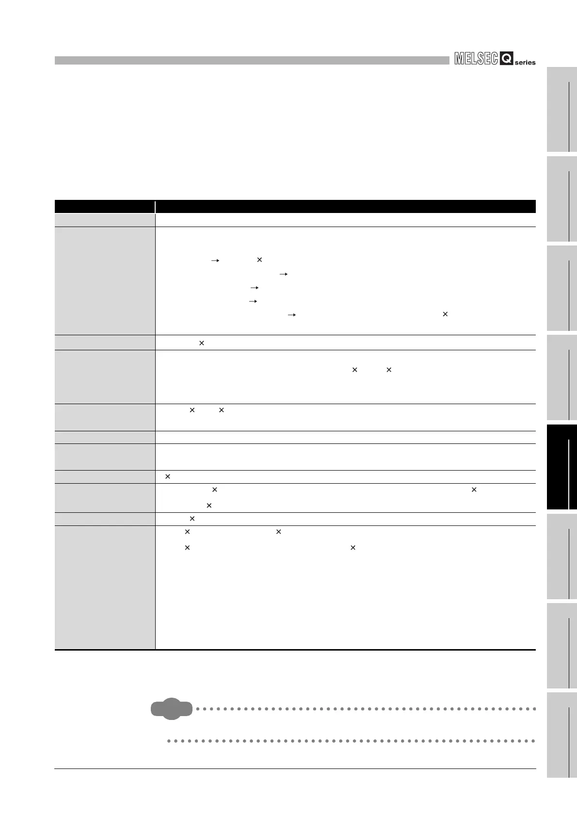
(2) When High Performance model QCPU, Process CPU or Redundant CPU
is used
When using the program memory, standard RAM, standard ROM or memory card,
calculate the rough size of each file according to Table5.11.
* 1 : 136 is the default value (increases depending on the parameter setting)
* 2 : The fractional portions of the (number of bit device points)/8, (total number of M and V points)/16
and (total number of T, ST and C points)/16 are rounded up.
Remark
Refer to Section 5.4.4 for the memory capacity calculation example.
Table5.11 Memory capacity calculation for files (High Performance model QCPU, Process CPU, Redundant CPU)
Function Rough file capacity (unit: byte)
Drive heading 64
Parameter
Default: 564 (increases depending on the parameter setting)
Reference
Boot setting 70 + (18 (number of files))
MELSECNET/H setting made Max. 4096/module increased
Ethernet setting made Max. 922/module increased
CC-Link setting made Max. 251/module increased
Remote password setting made 64 + 20 + (number of target modules 10), max. 164
increased
Sequence program
136
*1
+ (4 (number of steps) + (number of allocate memory for online program change)))
Device comment
74 + (sum of comment data sizes of devices)
• Comment data size of one device = 10 + 10250 a + 40 b
• a : Quotient of ((device points)/256)
• b : Remainder of ((device points)/256)
Device initial value
66 + 44 n + 2 (total number of device points set for the device initial value)
• n : Number of set device initial values
User setting area Value set at formatting (0 to 15k)
Multi-block online
program change
Value set at formatting (0/2k/4k)
File register 2 (number of file register points)
Sampling trace data
362 + (20 + 2 (number of word device points) + (number of bit device points)/8) (number of
traces) + 12 (device range)
*2
Failure history data 72 + 54 (number of failures stored)
Local device
72 + 6 (set device type) + (2 ((total number of M and V points)/16 + (number of D points)
+18 (total number of T, ST and C points)/16)) (number of programs)
*2
• M, V, D, T, ST and C indicate the following set devices.
M : Internal relay
V : Edge relay
D : Data register
T : Timer
ST : Retentive timer
C : Counter
 Loading...

